


OPS1200 User’s Manual
26
OPS1200 INTERCONNECT WIRING
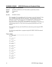
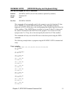
Communications (P5)
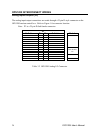
There is one 37 pin header provided on the OPS1200 communications board for the 2 serial
and 1 parallel communications ports. The two serial ports, COM1 and COM2, can be
individually configured as RS-232 or RS-422 interfaces. Configuration of the COM ports is
software selectable by the user. Refer to the ACR1200 Hardware Manual for details.
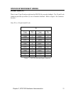
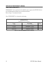
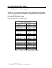
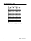
The following diagram shows the connections for the 3 communications ports. Refer to
Figure 1 for connector location.
Note: P5 is a 37-pin female D-sub.
P5
Usage Pin Usage Pin
RXD1 1 TXD1 20
GND 2 MUX1 21
TXD1A 3 TXD1B 22
RXD1A 4 RXD1B 23
RXD2 5 TXD2 24
GND 6 MUX2 25
TXD2A 7 TXD2B 26
RXD2A 8 RXD2B 27
STB 9 AFD 28
ERR 10 INIT 29
SLIN 11 GND 30
PD0 12 PD1 31
PD2 13 PD3 32
PD4 14 PD5 33
PD6 15 PD7 34
ACK 16 BUSY 35
PE 17 SLCT 36
N/C 18 N/C 37
N/C 19
Table 3.4 OPS1200 Communications Connector