


OPS1200 User’s Manual
24
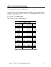
OPS1200 INTERCONNECT WIRING
Analog Inputs/Outputs (P2)
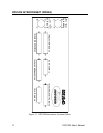
The analog input/output connections are made through a 25-pin D-style connector on the
OPS1200 motion control box. Refer to Figure 1 for connector location.
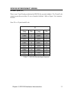
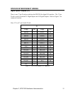
Note: P2 is a 25-pin D-Sub female connector.
P2
Definition Pin Pin Definition Module
ASIG-0 1 14 AGND-0 None
STEP-0 2 15 DIR-0
LCUR-0 3 16 SVCC
ASIG-1 4 17 AGND-1
STEP-1 5 18 DIR-1
LCUR-1 6 19 SVCC
AIN-0 7 20 AIN-1
AIN-2 8 21 AIN-3 ADC Module
AIN-4 9 22 AIN-5 P6
AIN-6 10 23 AIN-7
WD-COM 11 24 WD-NO None
WD-COM 12 25 WD-NC
AGND 13 ADC Module
Table 3.2 OPS1200 Analog I/O Connector