


IW4/IW7 WB/WBV Operations
D1 0412BA1-GB04 13
3 Operations
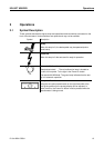
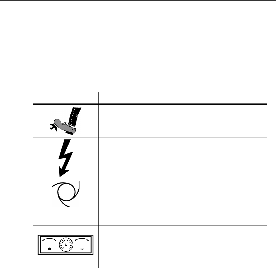
3.1 Symbol Description
These symbols describe the signal lamps and operational elements which are located on the
front of the test stand. Various switches are optional and may not be available.
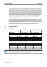
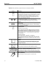
Symbol Description
Ready
When this lamp is lit, the brake pedal may be operated (and/or
Hand brake) .
Power ON
When this lamp is lit the test stand is ready for operation.
Automatic/Malfunction
Standard test stand: The red malfunction lamp is located on
the left of this symbol. To the right is the Power-On button.
Test stand with MB-Mode: The green lamp indicates that the test
rig is in automatic operation.
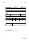
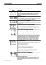
Zero point-Potentiometer
Using the zero-point potentiometer on the right hand side of the
test rig the pointers on the analog-display can be adjusted. In
order to do this, the Power-On button must be pressed while the
potentiometer is being turned.