


3 Cisco 6100 Series System Cables 78-6643-01 09/27/99
Cisco 6100 Series User Guide3-20
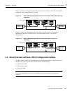
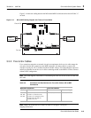
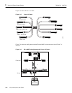
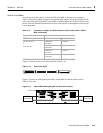
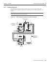
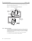
Figure 3-20 shows the cabling between the PSC and the external voice equipment in which the
cables listed in Table 3-10 are used.
Figure 3-20 PSC to External Voice Equipment Cabling Diagram with One-to-One Cables
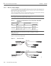
Two-to-Two Cables
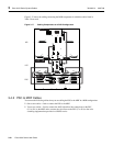
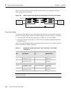
To associate the PSC MDF wire pairs and the MC modem ports, the two-to-two cable remaps the
wire pairsfrom the PSCMDF connectors tothe PSC connectors.You canuse the two-to-two cable to
• Connect the xDSL subscriber line connections on the PSC (J11 to J14) to the MDF
• Connect the voice lines on the PSC (J7 to J10) to the voice switching equipment that provides
local POTS service
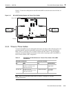
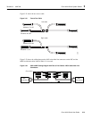
Table 3-11lists the backplane connectors andthe part numbers for thetwo-to-two cables connecting
the PSC to the MDF in a DOH configuration.
Note When you use the two-to-two cables, see Table C-8 on page C-26 for port
mapping information.
Table 3-11 Connectors and Part Numbers for Two-to-Two Cables—PSC to MDF
Connections
Backplane Connector Cisco Part Number
PSC MDF Modem Kit Subassembly
xDSL Subscriber Line Connectors
J11, J12 P1 (modems 1 to 16) or
P3 (modems 33 to 48)
CAB-PSC-80-REPIN 72-1716-01
(right cable)
J13, J14 P2 (modems 17 to 32) or
P4 (modems 49 to 64)
CAB-PSC-80-REPIN 72-1772-01
(left cable)
Voice Line Connectors
J7, J9 P1 (modems 1 to 16) or
P3 (modems 33 to 48)
CAB-PSC-80-REPIN 72-1716-01
(right cable)
J8, J10 P2 (modems 17 to 32) or
P4 (modems 49 to 64)
CAB-PSC-80-REPIN 72-1772-01
(left cable)
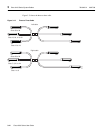
POTS
service
connections
27785
J3
J4
J8
J14
J2
J6
J10
J13
J36
J7
J11
J1
J5
J9
J12
POTS
service
connections
Cisco 6120