


78-6643-01 09/27/99 Cisco 6100 Series System Cables 3
Cisco 6100 Series User Guide 3-11
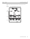
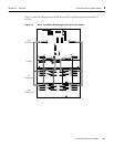
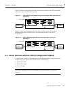
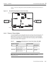
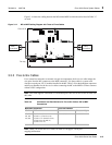
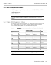
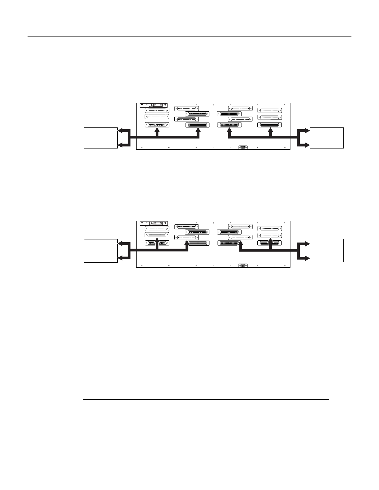
Figure 3-9 shows the cablingbetween the xDSL subscriberline connectors onthe PSC andthe MDF
in which the cables listed in Table 3-5 are used.
Figure 3-9 PSC toMDF Cabling Diagram with Two-to-Two Cables—xDSL Subscriber Line
Connectors
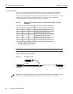
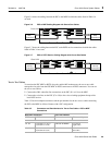
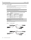
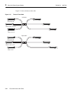
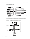
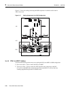
Figure 3-10 shows the cabling between the voice lines on the PSC and the voice switching
equipment that provides local POTS service. The cables listed in Table 3-5 are used for
the connection.
Figure 3-10 PSC to MDF Cabling Diagram with Two-to-Two Cables—Voice Line
Connectors
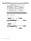
3.3 Direct Connect without a PSC Configuration Cables
In a Direct Connect without a PSC configuration, use only designated cables to connect the MC and
the MDF. This section provides tables and illustrations for the following:
• Two-to-three cables
• Three-to-three cables
• Five-to-six cables
Note Some chassis connectorsin the cabling diagramsare not used becausethey are specificto one
of the other configurations of the Cisco 6100 Series system or because they are reserved for
future use.
27320
J3
J4
J8
J14
J2
J6
J10
J13
J36
J7
J11
J1
J5
J9
J12
MDF
connections
MDF
connections
Cisco 6120
27784
J3
J4
J8
J14
J2
J6
J10
J13
J36
J7
J11
J1
J5
J9
J12
POTS
service
connections
POTS
service
connections
Cisco 6120