


78-6643-01 09/27/99 Cisco 6100 Series System Cables 3
Cisco 6100 Series User Guide 3-15
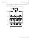
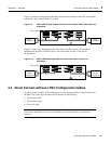
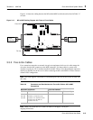
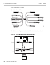
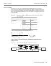
Figure 3-14 shows the cabling between the MC and the MDF in which the cables listed in Table 3-7
are used.
Figure 3-14 MC to MDF Cabling Diagram with Three-to-Three Cables
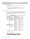
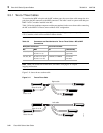
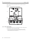
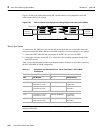
3.3.3 Five-to-Six Cables
For a convenient connection to external wire-pair test equipment, the five-to-six cable remaps the
wire pairs from the MC connectors to the MDF connectors. Use these cables in systems with
dual-port or quad-port xTU-C modulesinstalled in the MC. Table 3-8 lists the backplane connectors
and the part numbers for the five-to-six cables connecting the MC to the MDF in a Direct Connect
without a PSC configuration.
Note This cable supports a maximum of 120 modem ports. MC slots 20 and 38 are not used with
this cable.
Note When you use the five-to-six cable, see Table C-6 on page C-18 for port
mapping information.
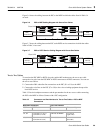
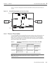
Table 3-8 Connectors and Part Numbers for Five-to-Six Cables—MC to MDF
Connections
Backplane Connector Cisco Part Number
MC MDF Kit Subassembly
J39, J40,
J41, J42
J43, J44
P1 (slots 1 to 6)
P2 (slots 7, 8, and 13 to 16)
P3 (slots 17 to 19 and 21 to 23)
P4 (slots 24 to 28, and 31)
P5 (slots 32 to 37)
CAB-MC-6:5-REPIN 72-1719-01
MDF
connections
Cisco 6130
27322
P14
P17
P15
E2A VISUAL AUDIBLE
FAN
ALARM
MIN
MAJ
CRIT
ACO
MIN
MAJ
CRIT
ACO
MIN
MAJ
CRIT
ANALOG TEST I/F
RING
TIP
P18
-48V_B
-48RTN
-48V_A
-48RTN
P13
MODEM
POOL
A
OUT
J45
J48
P3P9
J39
J42
MODEM
POOL
B
OUT
J46
J43
J44
J41
J40
J47
J49
P2
J1
Fan tray
FAN
P2
J1
-48VA
RTN
-48VB
RTN
MDF
connections