


User Connections 77
Connecting One Power Supply to a Single Load
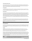
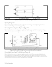
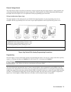
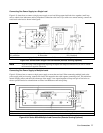
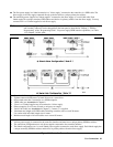
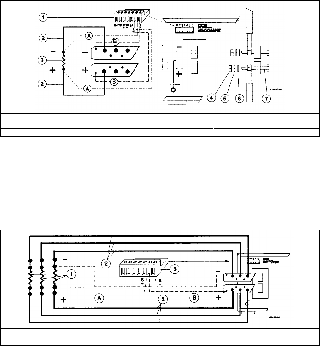
Figure 4-5c shows how to connect a single power supply to one load. Keep output load leads close together (small loop
area) to obtain a low inductance and low impedance connection to the load. If you wish to use remote sensing, connect the
sense leads at the load as shown in the figures.
Analog Connector ó Load Connection ì Load ö Nut
ú Lockwasher ÷ Flatwasher ø 3-8 inch bolt
A Connect for remote sensing (optional) B Connect for local sensing (default)
Figure 4-5c. Series 668xA Single Load Connection (Remote Sensing Optional)
Note If you are using a bench application requiring the Option 601 Output Connector Kit, be sure to consult
the instructions supplied with the kit.
Connecting One Power Supply to Multiple Loads
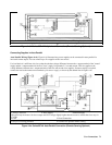
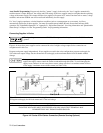
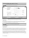
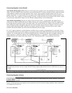
Figure 4-5d shows how to connect a single power supply to more than one load. When connecting multiple loads to the
power supply with local sensing, connect each load to the output bus bars with separate connecting wires. This minimizes
mutual coupling effects and takes full advantage of the supply’s low output impedance. Keep each pair of load wires as
short as possible and twist or bundle them to reduce lead inductance and noise pickup.
Load óLoad Connection ìAnalog Connector
A Connect for remote sensing (optional)
B
Connect for local sensing (default)
Figure 4-5d. Series 668xA Multiple Load Connection (Remote Sensing Optional)