


Digital Port Functions 123
Relay Link Operation
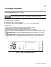
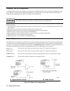
The digital port can be configured to provide relay control outputs for the Agilent 59510A or 59511A Relay Accessory.
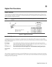
Refer to Figure D-1 for the pin assignments of the mating plug.
Not used with units that output more than 50 amps.
RLY SEND
(pin 1)
Provides the serial data to control the relays in the Relay Accessory.
(pin 2) (Not used)
RLY RTN
(pin 3)
Receives the data readback that indicates the status of the relays in the Relay Accessory.
Common
(pin 4)
Common connection for the RLY SEND and RLY RTN lines.
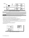
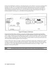
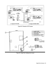
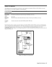
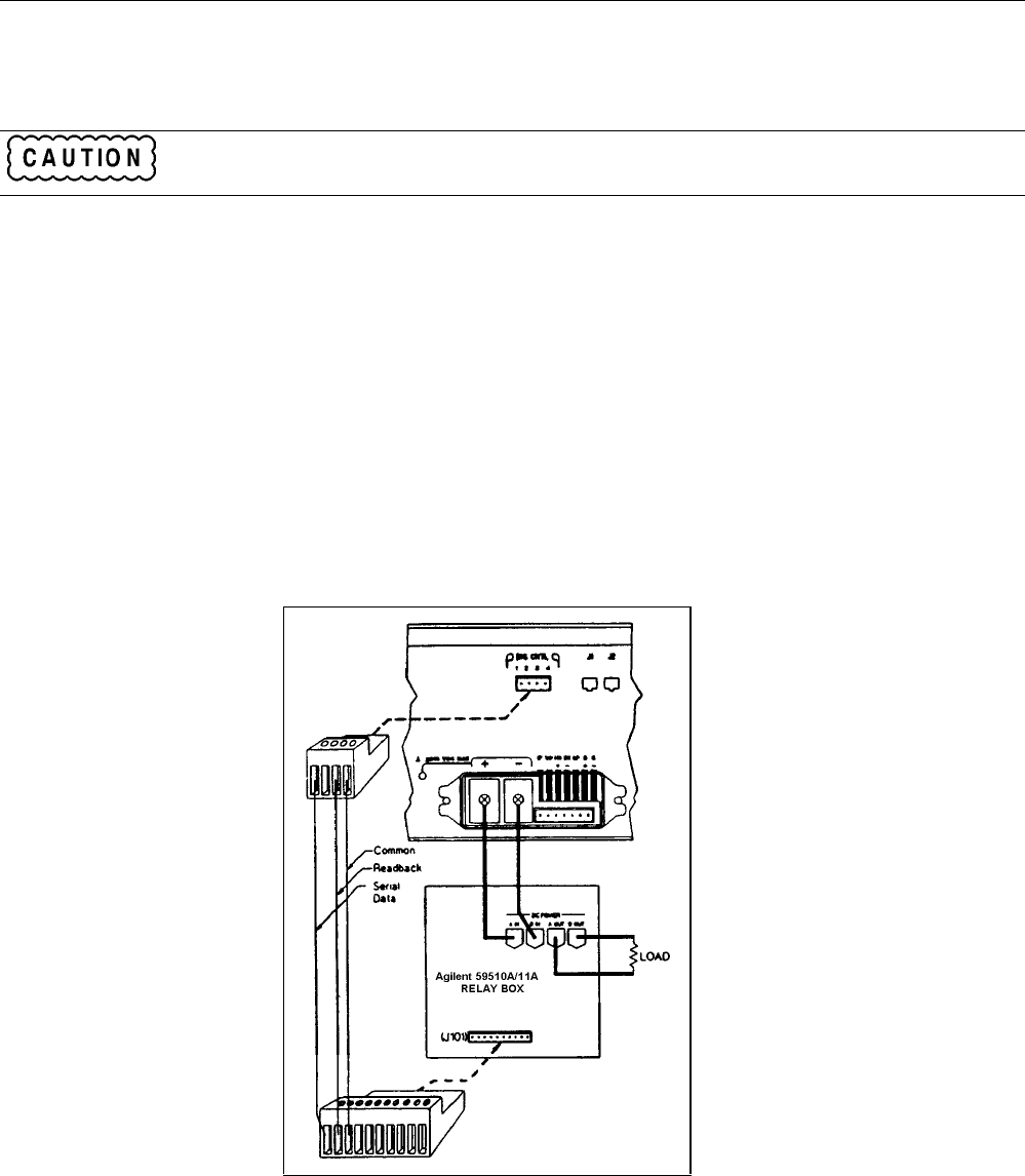
Figure D-6 shows how to connect your power supply to an Agilent 59510A or 59511A Relay Accessory when the digital
port is configured for relay link operation. An error will be generated if you attempt to program the relay box without first
configuring the digital port for relay link operation. For more information about programming the relay, refer to
OUTP:REL[:STAT] in Chapter 3 of the Programming Guide. For more information about the Relay Accessory, refer to its
manual (see Table 1-6).
Figure D-6. Relay Link Connections