


User Connections 73
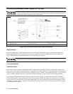
External Voltage Control
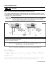
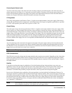
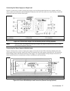
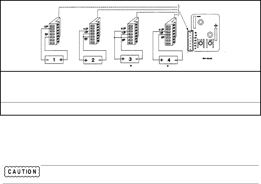
The setup shown in Figure 4-4g allows an external dc voltage to program the power supply output. A voltage applied to the
voltage programming input programs the output voltage and a voltage applied to the current programming input programs
the output current. See Figure 4-1 for an explanation of these programming input connections.
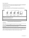
Wiring Considerations (Figure 4-4g)
The input impedance of the analog input is over 30 kΩ. If the output impedance of your programming source is not
negligible with this, programming errors will result. Larger output impedances result in proportionally greater errors.
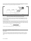
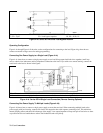
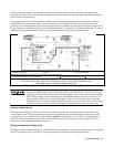
1 Voltage programming source 0 to -5V
2 Differential current programming source 0 to +10 V
3 Differential current programming source 0 to -10 V
4 Current programming source (floating) 0 to 10 V
* Maximum Potential between -IP and ↓P is ±15 V
Figure 4-4g. Series 667xA Analog Programming Connections
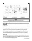
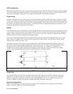
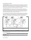
Programming
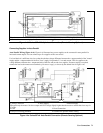
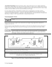
Note from Figure 4-1 that you have three options for programming the current. You can use a voltage source that is positive,
negative, or floating with respect to Common P. Do not exceed ±19 V with respect to Common P.
Make certain that the common connection for your voltage programming source is isolated from the
load. Failure to do this may cause damage to the power supply.
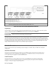
The effect of the analog programming source is always summed with the values programmed over the GPIB or from the
front panel. The voltage source can act alone only if you set the other program sources to zero. Keep the total programmed
setting of the supply (the analog input summed with the GPIB or front panel settings) at or under the output ratings specified
in Table 1-2a. Exceeding the output ratings will not damage the supply, but it may not be able to regulate its output at the
higher levels. If this happens, the Unr annunciator will light to warn you that the output is unregulated.