


User Connections 75
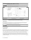
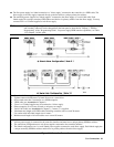
Inductive Loads
Inductive loads present no loop stability problems in CV mode. In CC mode, inductive loads will form a parallel resonance
with the power supply’s output capacitor, possibly causing current ringing in the load. For a given inductance, the power
supply’s CC control loop can be made to stabilize the current. However, stabilizing the current for a very large load
inductance creates a much slower mode crossover (CV to CC or vice versa) time. Thus, there is a tradeoff between mode
crossover speed and inductive compensation. To allow an optimal solution for each load, a CC loop compensation switch is
provided so the CC control loop can be optimized for a specific load inductance. See "Appendix E - Current Loop
Compensation" for details.
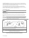
Battery Charging
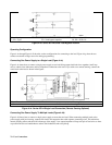
The power supply’s OVP circuit has a downprogrammer FET that discharges the power supply output whenever OVP trips.
If a battery (or other external voltage source) is connected across the output and the OVP is inadvertently triggered or the
output is programmed below the battery voltage, the power supply will sink current from the battery. To avoid this, insert a
reverse blocking diode in series with the ⊕ output of the supply. Connect the diode cathode to the + battery terminal and
the diode anode to the supply ⊕ output terminal. The diode will require a heat sink.
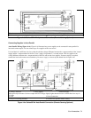
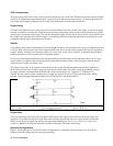
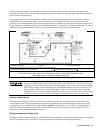
Local Voltage Sensing
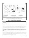
For local sensing the +S and--S analog connector pins must be connected to the + and - bus bars (see Figure 4-5b). This is
the default configuration as wired at the factory. Each sense lead is connected to the small, tapped hole nearest the
corresponding output lead. Since local sensing does not compensate for voltage drops in the screw connections or load
leads, local sensing should only be used in applications that require low output currents or where load regulation is not
critical.
Note If the sense terminals are left open, the voltage at the output bus bars will increase approximately 3 to 5%
over the programmed value. The readback voltage will not reflect this increase because readback is
measured at the sense terminals.
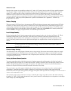
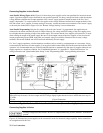
Remote Voltage Sensing
The dashed lines in the wiring diagrams illustrate remote voltage sensing. The remote sense terminals of the power supply
are connected directly to the load rather than to the output bus bars. This allows the supply to automatically increase the
voltage at the output bus bars to compensate for any voltage drop in the load leads, as well as to accurately read back the
voltage directly from the load.
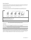
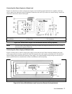
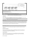
Setting Up Remote Sense Operation
You must connect the positive side of the load to the +S analog connector pin and the negative side of the load to the -S
analog connector pin (see Figure 4-1). Connect the sense leads carefully so that they do not become open-circuited. If sense
leads are left open during operation, the supply will regulate at the output bus bars instead of at the load. Remember to
bundle or tie wrap the load leads to minimize inductance and reduce noise pickup.
The sense leads are part of the supply’s feedback path and must be kept at a low resistance in order to maintain optimal
performance. Connect the sense leads carefully so that they do not become open-circuited. If the sense leads are left
unconnected or become open during operation, the supply will regulate at the output bus bars, resulting in a 3 to 5% increase in
output over the programmed value.
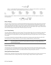
The maximum output voltage under remote sensing is reduced by the voltage drop in the load leads. See “Remote Sensing
Capability” in Table 1-3b for further characteristics and a general formula for determining the extra degradation in the output
due to voltage drop in the output leads.