


User Connections 61
Note If the sense terminals are left unconnected, the voltage at the bus bars will increase approximately 3 to 5%
over the programmed value. Since it is measured at the sense terminals, the voltage readback will not
reflect this increased output.
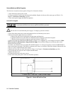
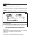
Remote Voltage Sensing
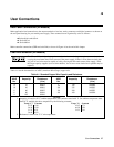
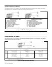
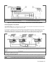
The dashed lines in the wiring diagrams illustrate remote voltage sensing. The remote sense terminals of the power supply
are connected directly to the load rather than to the output terminals. This allows the supply to automatically compensate for
the voltage drop in the load leads as well as to accurately read back the voltage directly across the load.
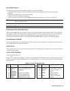
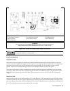
Setting Up Remote Sense Operation
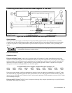
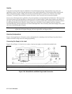
Remote sensing is obtained by placing the SENSE switch (see Figure 4-3a) in the Remote position. The power supply is
shipped with the switch in the Local position.
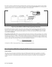
Connecting The Sense Leads
You must connect the positive side of the load to the +S analog connector pin and the negative side of the load to the
-S analog connector pin (see Figure 4-1). Connect the sense leads carefully so that they do not become open-circuited. If
sense leads are left open during operation, the supply will regulate at the output terminals instead of at the load. Remember
to bundle or tie wrap the load leads to minimize inductance and reduce noise pickup.
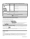
CV Regulation
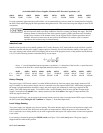
The voltage load regulation specification in Table 1-la and Table 1-2a applies at the output terminals of the power supply.
When remote sensing, this specification must be compensated. Add 3 mV to the voltage load regulation specification for
each 1-volt change in the positive load lead due to a change in load current. Because the sense leads are part of the supply’s
feedback path, keep the resistance of the sense leads at or below 0.5 Ω to maintain the above specified performance.
OVP Considerations
The OVP circuit senses the voltage near the output terminals, not at the sense terminals. The voltage sensed by the OVP
circuit can be significantly higher than the voltage being maintained at the load. When using remote sensing, you must
program the OVP high enough to compensate for the expected voltage drop between the output and the load.
Output Rating
The rated output voltage and current specification in Table l-la and Table 1-2a applies at the output terminals of the power
supply. With remote sensing, any voltage dropped in the load leads causes the supply to increase the voltage at the output
terminals so it can maintain the proper voltage at the load. When you attempt to operate at the full-rated output at the load,
this forces the supply voltage at the output terminals to exceed the supply’s rated output.
This will not damage the supply, but may trip the OVP (overvoltage protection) circuit, which senses the voltage at the
output. When operated beyond its rated output, the supply’s performance specifications are not guaranteed, although typical
performance may be good. If the excessive demand on the supply forces it to lose regulation, the Unr annunciator will
indicate that the output is unregulated.
Output Noise
Any noise picked up on the sense leads also appears at the output of the power supply and may adversely affect the load
voltage regulation. Be sure to twist the sense leads to minimize external noise pickup and route them parallel and close to
the load leads. In noisy environments, it may be necessary to shield the sense leads. Ground the shield only at the power
supply. Do not use the shield as one of the sense conductors.