HUAWEI MG323 GSM M2M Module
Electrical and Reliability Features
Issue 06 (2013-06-13)
Huawei Proprietary and Confidential
Copyright © Huawei Technologies Co., Ltd.
37
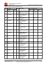
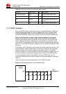
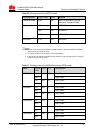
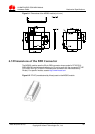
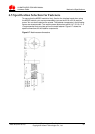
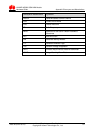
Pin No. Signal Name Pin No. Signal Name
11 GND 12 INTMIC_P
13 NC 14 EXTMIC_P
15 NC 16 EXTMIC_N
17 NC 18 GND
19 NC 20 TERM_ON
21 NC 22 RESET
23 NC 24 UART1_DCD
25 LED_STATUS 26 NC
27 NC 28 UART1_CTS
29 UART1_RD 30 NC
31 NC 32 UART1_DTR
33 UART1_TD 34 UART1_RTS
35 VCOIN 36 UART1_DSR
37 NC 38 UART1_RING
39 NC 40 VIO
41 GND 42 VBAT
43 GND 44 VBAT
45 GND 46 VBAT
47 GND 48 VBAT
49 GND 50 VBAT
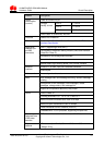
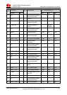
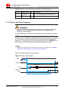
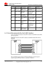
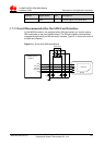
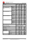
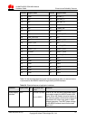
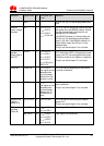
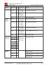
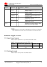
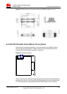
Table 5-4 lists electrical features (typical values) measured when no external device
is connected to the MG323 module through the 50-pin B2B interface.
Table 5-4 Electrical features of application interfaces
Function Signal Name I/O
Waveform and
Level
Remarks
Power supply
interface
VBAT P
V
I
=3.30 V to 4.80
V
V
Itypical
=3.80 V
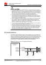
Pins 42, 44, 46, 48, and 50 are power supply
pins used to supply the MG323 module with
power. When the module transmits signals at
the maximum power, the transient current can
reach about 2 A, which may result in VBAT
voltage great drop. The VBAT power voltage
for the MG323 module should not be lower
than 3.3 V.