HUAWEI MG323 GSM M2M Module
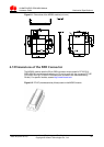
Description of the Application Interfaces
Issue 06 (2013-06-13)
Huawei Proprietary and Confidential
Copyright © Huawei Technologies Co., Ltd.
16
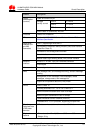
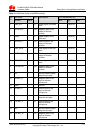
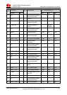
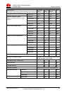
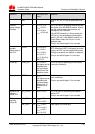
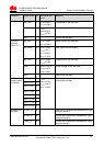
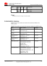
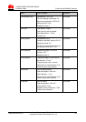
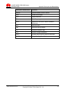
Pin
No.
Pin Name I/O Description DC Characteristics (V)
Normal MUX Min. Tpy. Max
39 NC - -
Not connected, please
keep this pin open
- - -
40 VIO - P External power output 2.70 2.80 2.95
41 GND - - Ground - - -
42 VBAT - P Power supply input 3.30 3.80 4.80
43 GND - - Ground - - -
44 VBAT - P Power supply input 3.30 3.80 4.80
45 GND - - Ground - - -
46 VBAT - P Power supply input 3.30 3.80 4.80
47 GND - - Ground - - -
48 VBAT - P Power supply input 3.30 3.80 4.80
49 GND - - Ground - - -
50 VBAT - P Power supply input 3.30 3.80 4.80
P indicates power pins; I indicates pins for digital signal input; O indicates pins for digital
signal output; AI indicates pins for analog signal input; AO indicates pins for analog signal
input.
The NC (Not Connected) pins are internally connected to the module. Therefore, these pins
should not be used, otherwise they may cause problems. Please contact us for more
details about this information.
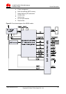
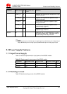
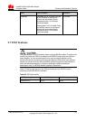
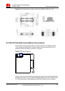
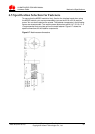
3.3 Power Interface
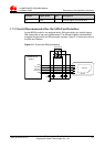
3.3.1 Overview
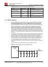
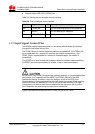
The power supply part of the B2B interface of the MG323 module contains:
VBAT interface for the power supply
VCOIN interface for the standby power supply of the real-time clock (RTC)
VIO interface for external power output
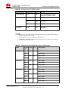
Table 3-2 lists the definitions of the pins on the power supply interface.