HUAWEI MG323 GSM M2M Module
Description of the Application Interfaces
Issue 06 (2013-06-13)
Huawei Proprietary and Confidential
Copyright © Huawei Technologies Co., Ltd.
21
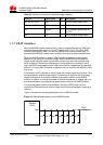
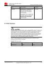
Network status LED (LED_STATUS) pin
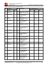
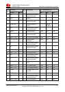
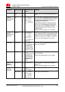
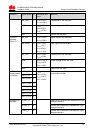
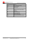
Table 3-4 lists the pins on the signal control interface.
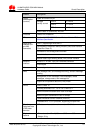
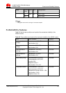
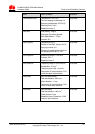
Table 3-4 Pins on the signal control interface
Pin No. Signal Name I/O Description
20 TERM_ON I Pin for controlling power-on and power-off
22 RESET I Pin for resetting the hardware
25 LED_STATUS O Pin for network status LED
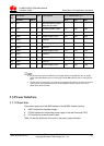
3.5.2 Input Signal Control Pins
The MG323 module implements power-on and power-off and resets the hardware
through the input signal control pins.
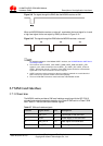
The TERM_ON pin is used to implement power-on and power-off. If the TERM_ON
pin is pulled down for 1 second to 2 seconds, the module is powered on; if the
TERM_ON pin is pulled down for 1 second to 2 seconds again, the module is
powered off.
The RESET pin is used to reset the hardware. When the software stops responding,
the RESET pin can be pulled down for at least 10 ms to reset the hardware.
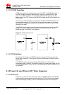
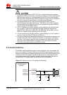
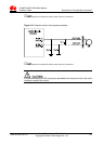
As the RESET and TERM_ON signals are relatively sensitive, it is recommended that
you install a 10 nF capacitor near the RESET and TERM_ON pins of the B2B
interface for filtering. In addition, when you design a circuit on the PCB of the
interface board, it is recommended that the circuit length not exceed 20 mm and that
the circuit be kept at a distance of 2.54 mm (100 mil) at least from the PCB edge.
Furthermore, you need to wrap the area adjacent to the signal wire with a ground
wire. Otherwise, the module may be reset due to interference.
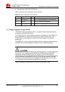
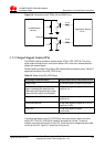
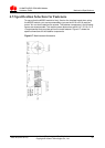
Figure 3-6 shows the connections of the TERM_ON and RESET pins.