HUAWEI MG323 GSM M2M Module
Description of the Application Interfaces
Issue 06 (2013-06-13)
Huawei Proprietary and Confidential
Copyright © Huawei Technologies Co., Ltd.
27
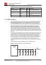
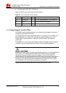
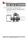
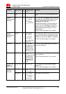
To meet the requirements of 3GPP TS 51.010-1 protocols and electromagnetic
compatibility (EMC) authentication, the SIM card socket should be placed near the
B2B connector interface (it is recommended that the PCB circuit connecting the
B2B connector interface and the SIM card socket not exceed 100 mm), because a
long circuit may lead to wave distortion, thus affecting signal quality.
It is recommended that you wrap the area adjacent to the SIM_CLK and
SIM_DATA signal wires with a ground wire. The GND pin of the SIM card socket
and the GND pin of the SIM card must be well connected to the power GND pin
supplying power to the MG323 module.
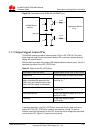
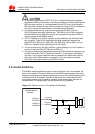
A 0.1 µF capacitor or a 0.22 µF capacitor is placed between the VSIM and GND
pins in parallel. Three 33 pF capacitors are placed respectively between the
SIM_DATA and GND pins, the SIM_RST and GND pins, and the SIM_CLK and
GND pins in parallel to filter interference from RF signals.
You do not need to pull the SIM_DATA pin up during design as a 15 kΩ resistor is
used to connect the SIM_DATA pin to the VSIM pin.
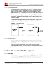
It is recommended to take electrostatic discharge (ESD) protection measures near
the SIM card socket. The TVS diode with Vrwm of 5 V and junction capacitance
less than 10 pF must be placed as close as possible to the SIM socket, and the
Ground pin of the ESD protection component is well connected to the power
Ground pin that supplies power to the MG323 module.
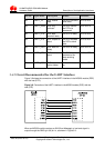
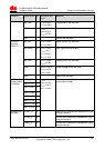
3.8 Audio Interface
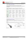
The MG323 module provides two types of audio interfaces: one is for handsets, the
other is for headsets. The audio interfaces of the MG323 module support input from
handset microphones and headset microphones, and provide output that supports 32
Ω handsets and 16 Ω headsets. Differential signal lines are recommended for the
microphone interface and the speaker interface. Single-ended signal lines are not
recommended. The reception gain can be adjusted by using software.
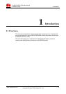
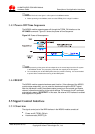
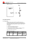
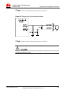
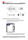
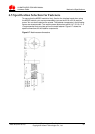
Figure 3-12 External circuit for 32 Ω handsets/16 Ω headsets
INTEAR_P/
EXTEAR_P
INTEAR_N/
EXTEAR_N
ESD protection
33 pF
ferrite bead
ferrite bead
Speaker
33 pF
100 pF
+
-
HUAWEI Module
(Modem)