HUAWEI MG323 GSM M2M Module
Description of the Application Interfaces
Issue 06 (2013-06-13)
Huawei Proprietary and Confidential
Copyright © Huawei Technologies Co., Ltd.
22
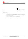
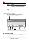
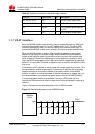
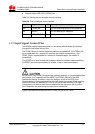
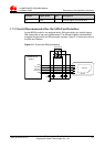
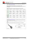
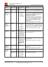
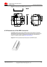
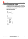
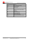
Figure 3-6 Connections of the TERM_ON and RESET pins
Application Device
(Host)
2.2 kΩ
RESET
TERM_ON
2.2 kΩ
10 nF
10 nF
b
b
c
e
c
e
HUAWEI Module
(Modem)
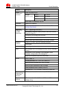
3.5.3 Output Signal Control Pin
The MG323 module provides a network status LED pin LED_STATUS. The pulse
signal output through this pin controls the status LED on the user interface board to
display the network status.
Different blinking modes of the status LED indicate different network status. Table 3-5
describes the status of the LED_STATUS pin.
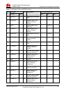
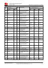
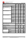
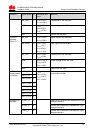
Table 3-5 Status of the LED_STATUS pin
Working or Network Status Output Status of the LED_STATUS Pin
Sleep mode A low-level signal is output continuously.
Network-searching or non-network
status (including the case when the
SIM card is not inserted and the case
when the PIN number is unblocked)
A high-level signal is output for 0.1s in a
period of 1s.
Registered with a 2G network
A high-level signal is output for 0.1s in a
period of 3s.
GPRS data service
A high-level signal is output for 0.1s in a
period of 0.125s.
Voice call
A high-level signal is output
continuously.
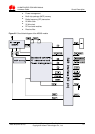
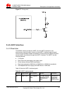
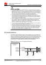
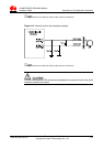
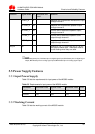
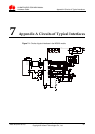
In practical application, the LED_STATUS pin cannot be directly used to drive the
status LED. The LED_STATUS pin needs to be used with a triode. To select a
suitable current-limiting resistor for the LED, check the actual voltage drop and rated
current of the LED. Figure 3-7 shows the driving circuit.