HUAWEI MG323 GSM M2M Module
Electrical and Reliability Features
Issue 06 (2013-06-13)
Huawei Proprietary and Confidential
Copyright © Huawei Technologies Co., Ltd.
40
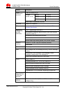
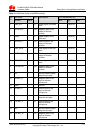
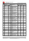
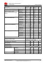
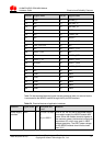
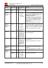
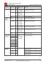
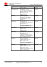
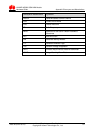
Function Signal Name I/O
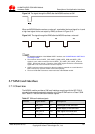
Waveform and
Level
Remarks
INTMIC_N AI
Negative end of differential handset MIC input
through channel 1
EXTEAR_N AO
Negative end of differential speaker output
through channel 2
EXTEAR_P AO
Positive end of differential speaker output
through channel 2
INTEAR_P AO
Positive end of differential speaker audio
output through channel 1
INTEAR_N AO
Negative end of differential speaker audio
output through channel 1
NC pin NC
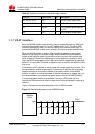
Pins 9, 13, 15, 17, 19, 21, 23, 26, 27, 30, 31,
and 39 are internal pins. These pins need to
be left floating when they are used.
P indicates power pins; I indicates pins for digital signal input; O indicates pins for digital signal
output; AI indicates pins for analog signal input; AO indicates pins for analog signal output.
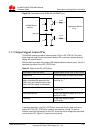
5.5 Power Supply Features
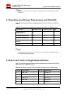
5.5.1 Input Power Supply
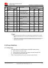
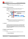
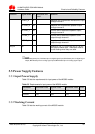
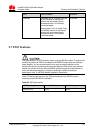
Table 5-5 lists the requirements for input power of the MG323 module.
Table 5-5 Requirements for input power of the MG323 module
Parameter Minimum Value Typical Value Maximum Value Unit
VBAT 3.30 3.80 4.80 V
VCOIN 2.00 3.00 3.15 V
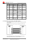
5.5.2 Working Current
Table 5-6 lists the working current of the MG323 module.