HUAWEI MG323 GSM M2M Module
Description of the Application Interfaces
Issue 06 (2013-06-13)
Huawei Proprietary and Confidential
Copyright © Huawei Technologies Co., Ltd.
25
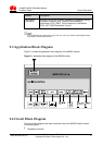
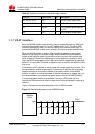
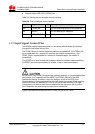
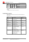
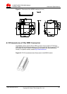
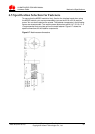
Figure 3-9 The signal through the RING after the MG323 receives an SM
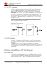
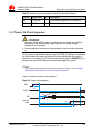
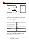
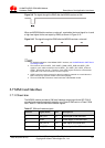
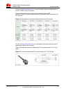
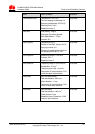
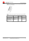
When an MG323 Module receives a voice call, a periodical low level signal for 1s and
a high level signal for 4s are output by RING, as shown in Figure 3-10 .
Figure 3-10 The signal through the RING after the MG323 receives a voice call
For detailed application of the MG323 UART1 interface, see HUAWEI Module UART Serial
Port Design Guide.
The maximum level of UART1_DCD, UART1_RING, UART1_DSR and UART1_DTR
signals is 3.2 V, and the maximum level of UART1_TD, UART1_RD, UART1_CTS and
UART1_RTS signals is 3.25 V. Therefore, if the UART signals need to be connected the
signal with 3.3 V, a level conversion curcuit is required.
UART1 interface must be powered on after the module is powered on to avoid the wind
blow in which may cause the module cannot work properly.
The level of RS-232 Transceivers must match that of the MG323 module.
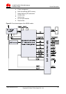
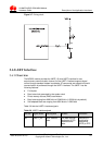
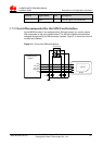
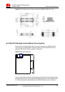
3.7 SIM Card Interface
3.7.1 Overview
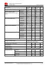
The MG323 module provides a SIM card interface complying with the ISO 7816-3
standard and supports automatic detection of a Class B SIM card or a Class C SIM
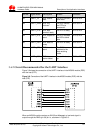
card. Table 3-7 lists the SIM card interface signals.
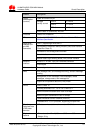
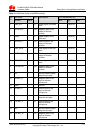
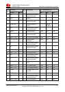
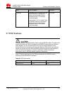
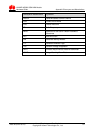
Table 3-7 SIM card interface signals
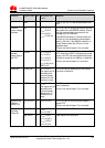
Pin No. Signal Name I/O Description
1 SIM_CLK O Clock signal of the SIM card
3 VSIM P Power supply of the SIM card
5 SIM_DATA I/O Data signal of the SIM card
7 SIM_RST O Reset signal of the SIM card