98
Examples
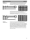
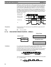
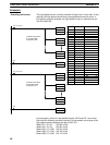
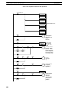
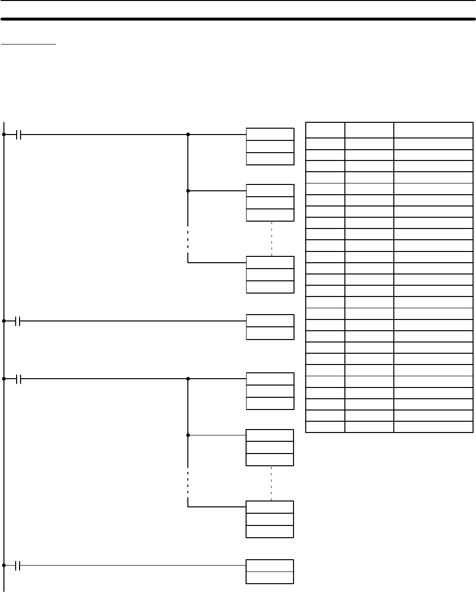
The high-speed counter normally provides 16 output bits. If more than 16 are
required, the high-speed counter may be programmed more than once. In
the following program example, the high-speed counter is used twice to pro-
vide 32 output bits.
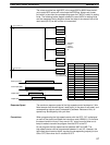
1813 (normally ON)
0002
MOV(21)
“S1”
DM 32
MOV(21)
“S2”
DM 33
MOV(21)
“S32”
DM 35
HDM(61) 47
HR 0
Transfers limit values
S1 to S32 to DM.
Output thru HR 0
A
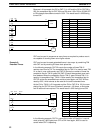
1813 (normally ON)
0002
MOV(21)
Transfers limit values
S33 to S64 to DM.
Output thru HR 1
B
“S33”
DM 32
MOV(21)
“S34”
DM 33
MOV(21)
“S64”
DM 35
HDM(61) 47
HR 1
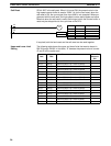
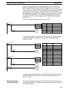
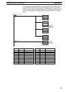
Address Instruction Operands
0000 LD 1813
0001 MOV(21)
“S1”
DM 32
0002 MOV(21)
“S2”
DM 33
0003 MOV(21)
“S32”
DM 35
0004 LD 0002
0005 HDM(61) 47
HR 0
0006 LD 1813
0007 MOV(21)
“S33”
DM 32
0008 MOV(21)
“S34”
DM 33
0009 MOV(21)
“S64”
DM 35
0010 LD 0002
0011 HDM(61) 47
HR 1
In this program, each bit in the specified words, HR 0 and HR 1 are turned
ON under the following conditions (where S is the present count value of the
high-speed counter stored as the data of CNT 47):
Where S1 ≤ S ≤ S2, HR 000 is ON.
Where S3 ≤ S ≤ S4, HR 001 is ON.
Where S31 ≤ S ≤ S32, HR 015 is ON.
Where S33 ≤ S ≤ S34, HR 100 is ON.
Where S63 ≤ S ≤ S64, HR 115 is ON.
Extending the Counter
Timer and Counter Instructions Section 5-11


