


16
POINT
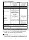
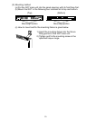
(1) Use the thickest possible (max. 2 mm
2
(14 AWG)) wires for the
100/200 VAC and 24 VDC power cables. Be sure to twist these wires
starting at the connection terminals. To prevent a short-circuit should
any screws loosen, use solderless terminals with insulation sleeves.
(2) When the LG terminals and FG terminals are connected, be sure to
ground the wires. Do not connect the LG terminals and FG terminals
to anything other than ground. If LG terminals and FG terminals are
connected without grounding the wires, the PLC may be susceptible
to noise.
In addition, since the LG terminals have potential, the operator may
receive an electric shock when touching metal parts.
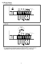
5.6 Connection Cable Wiring
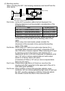
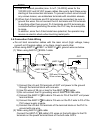
• Do not bind connection cables with the main circuit (high voltage, heavy
current) or I/O signal cables, or lay them close to each other.
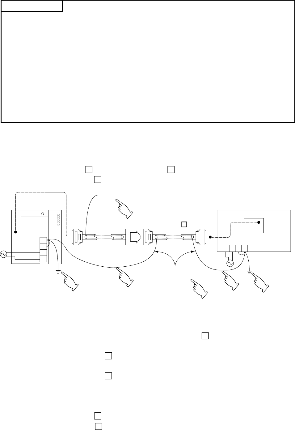
• When using A8GT-C
EXSS-1 or A8GT-C BS, ground wires as below.
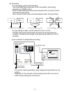
(1) When using A8GT-C
EXSS-1 cable
FG
LG
N
L
PLC
Disconnected
(A8GT-EXCNB)
GOT
OUT
IN
FGLG
NL
2SQ wire FG terminal,
28 cm or less
(A8GT-C BS)
6)
5)
2)
4)
1)
3)
1) Connect the LG and FG terminals of GOT unit power to the ground
through the terminal block with one wire.
2) Use FG wires of 28 cm or less for the A8GT-C
BS cable.
3) Do not connect the FG grounding wire of A8GT-EXCNB cable.
4) Connect the A8GT-C
BS cable’s FG wire to FG of the GOT unit power
terminal block.
5) Connect the A8GT-C
BS cable’s FG wire on the PLC side to FG of the
PLC power supply module.
6) Connect the LG and FG terminals of the terminal block on the PLC to
ground with one wire.
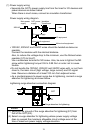
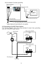
(2) When using A8GT-C
BS cable
Connect the A8GT-C
BS cable
’
s FG wires on the both sides to the FG
terminals on the power terminal block of the both side GOTs.