


9
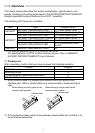
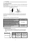
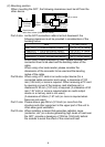
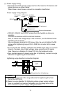
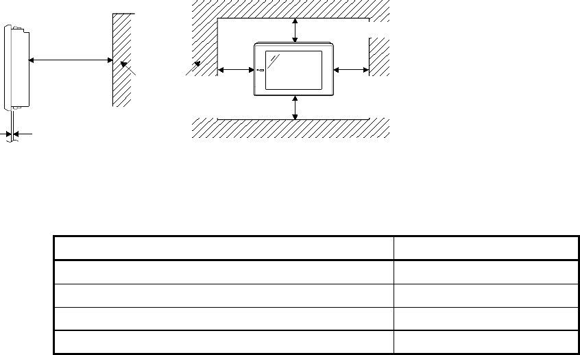
(2) Mounting position
When mounting the GOT, the following clearances must be left from the
other device.
(100mm
(3.94 inch)
or more)
A
Plate thickness
within 2mm to 4mm (0.08inch to 0.16inch)
Other
device
(80mm (3.15 inch) or more)
(50mm
(1.97inch)
or more)
(50mm
(1.97inch)
or more)
D
BB
C
Part A size: As the GOT connection cable is led out downward, the
following clearance must be provided in consideration of the
bending radius.
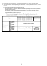
Item A [mm] (inch)
A97*GOT + Communication board 130 (5.12) or more
A960GOT + Communication board 140 (5.51) or more
A97*GOT + A9GT-BUSSU/BUS2SU 15 (0.59) or more
A960GOT + A9GT-BUSSU/BUS2SU 30 (1.18) or more
When using a cable prepared by user, please consider the
connector cover to be used and the bending radius of the
cable.
When using a bar code reader, please consider the
dimensions of the connector to be used and the bending
radius of the cable.
Part B size: When using a PC card or an audio output device (for a
connected cable connector and a wire), a clearance of 100
mm (3.94 inch) or more is required. When removing a PC card
by opening a cover of the memory card interface part, a
clearance of 50 mm (1.97 inch) is required. (A clearance of 50
mm (1.97 inch) or more is required when an audio output
device or a memory card is not used.)
(A clearance of 50mm (1.97 inch) or more is required when
these are not used.)
Part C size: Please allow a gap 80mm (3.15inch) or more from the
structure and other equipment in the upper part of the unit to
often allow good ventilation.
Part D size: When installing a device that generates radiation noise
(contactor, etc.) or a device generating high levels of heat near
the GOT, provide a clearance of 100mm (3.94 inch) behind
the module to avoid the effect of the noise and heat.