


13
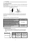
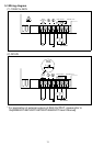
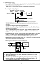
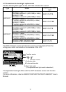
(1) Power supply wiring
y Separate the GOT's power supply line from the lines for I/O devices and
power devices as shown below.
When there is much noise, connect an insulation transformer.
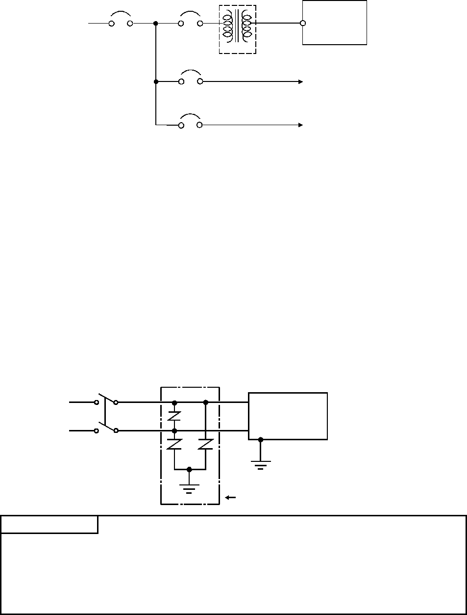
Power supply wiring diagram
200VAC
T1
Main power
supply
GOT power
supply
Insulation
Transformer
GOT
I/O power supply
Main circuit equipment
I/O equipment
Main circuit equipment
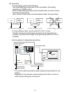
y 100VAC, 200VAC and 24VDC wires should be twisted as dense as
possible.
Connect the modules with the shortest distance.
Also, to reduce the voltage drop to the minimum, use the thickest wires
possible (0.75 to 2mm
2
).
Use a solderless terminal for M3 screw. Also, be sure to tighten the M3
screw within tightening torque 0.55 to 0.88 Nym in order not to cause
trouble.
y Do not bundle the 100VAC, 200VAC and 24VDC wires with, or run them
close to, the main circuit (high voltage, large current) and I/O signal
lines. Reserve a distance of at least 100 mm from adjacent wires.
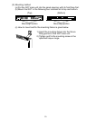
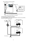
y As a countermeasure to power surge due to lightening, connect a surge
absorber for lightening as shown below.
Lightening surge absorber connection diagram
AC
E1
E2
GOT
Surge absorber for lightening
POINT
(1) Separate the ground of the surge absorber for lightening (E1) from
that of the GOT (E2).
(2) Select a surge absorber for lightening whose power supply voltage
does no exceed the maximum allowable circuit voltage even at the
time of maximum power supply voltage elevation.