


7
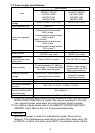
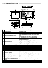
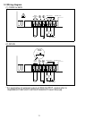
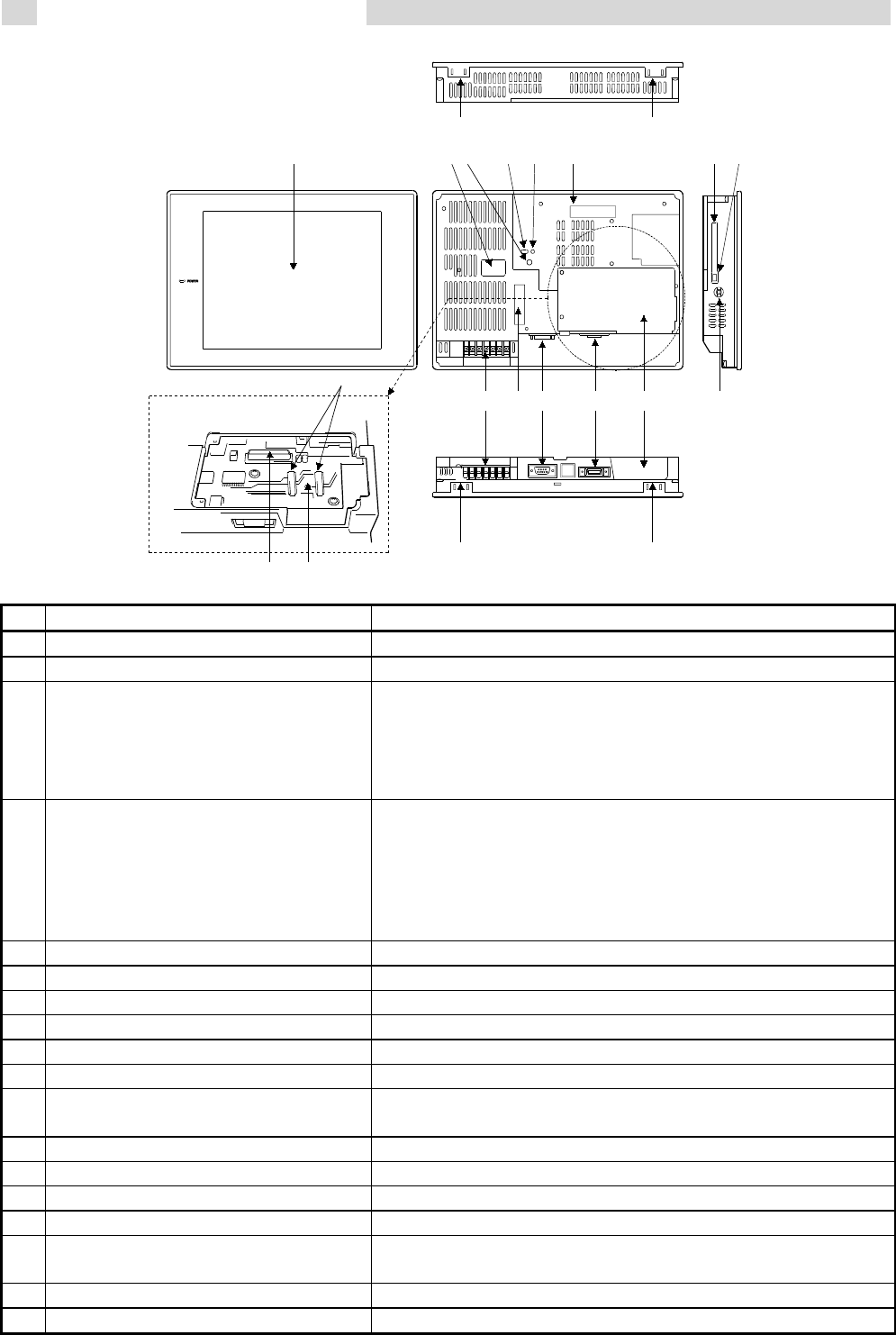
4. Name of the Parts
1) 2) 3) 4) 5) 6) 7)
13) 12)11) 10)
9) 8)
17) 17)
17) 17)
18)
When 9) is removed
14) 16)
15)
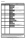
No. Name Description
1
)
Display section Shows the screen
2
)
Reset button Used to reset the hardware of the GOT
3
)
memory card access switch
Used to set the condition of access to the PC card
when it is loaded during power-on (Factory-set to
OFF)
OFF: Access from GOT to PC card inhibited
ON : Access from GOT to PC card enabled
4
)
memory card LED
Indicates whether the PC card may be
loaded/unloaded or not
Off: PC card may be loaded/unloaded
(When switch 3 is OFF)
On: PC card must not be loaded/unloaded
(When switch 3 is ON)
5
)
Communication module interface Interface for loading the communication module
6
)
memory card interface Interface for loading the PC card
7
)
memory card ejection button Button used to withdraw the PC card
8
)
Speech output terminal For external speaker connection
9
)
Slot cover Fixture to cover the slot
10
)
Printer interface For printer connection
11
)
RS-232C interface
For connection of personal computer
For connecting the bar code reader
12
)
Option module interface For option module loading (for future extension)
13
)
Terminal block For power input and external output
14
)
Communication board slot Slot for communication board loading
15
)
Memory board slot Slot for memory board loading
16
)
Screw hole for attaching memory
board
Screw hole used to attach the memory board
17
)
Mounting fixture fitting portion For mounting fixture fitting
18
)
Rating plate ⎯⎯⎯⎯