


42
4. L.E.D. DISPLAY INDICATOR NUMBER 4
a. On Indicator:
1) This indicator dot is on whenever a cycle is in progress. Additionally, when the Anti-Wrinkle
program is active, the indicator dot
will be on whenever the Phase 6 OPL microprocessor controller
(computer) is in the Guard On Time program.
5. L.E.D. DISPLAY INDICATOR NUMBER 5
a. Air Jet Circuit - OPTIONAL
1) This indicator dot is on at the end of the dryer cycle for approximately 60 seconds.
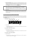
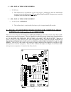
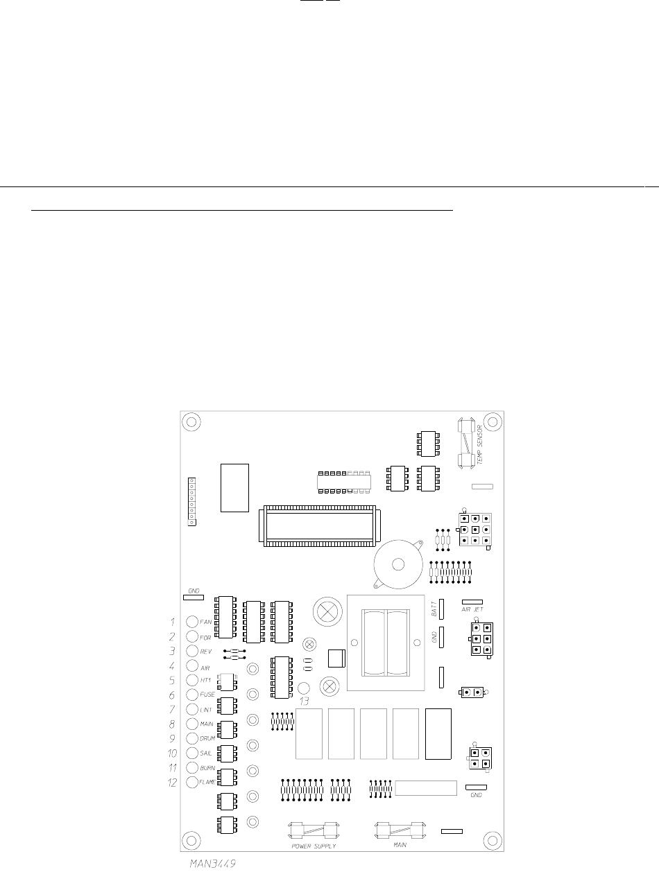
C. PHASE 6 OPL MICROPROCESSOR CONTROLLER (COMPUTER) RELAY
OUTPUT L.E.D. (light emitting diode) INDICATORS
There are a series of five (5) L.E.D. indicators (ORANGE LIGHTS) located at the backside of the Phase 6 OPL
microprocessor controller (computer). These are identified or labeled (from top to bottom in the illustration below
as: FAN-BLOWER, FOR-FORWARD, REV-REVERSE, AIR-AIR-JET, HT1-HEAT OUTPUT. There are a
series of seven (7) L.E.D. indicators (red lights) FUSE-MAIN FUSE, LINT-LINT DOOR, MAIN-MAIN
DOOR, DRUM-TUMBLER HI-LIMIT, SAIL-SAIL SWITCH, BURN-BURNER HI LIMIT, FLAME-FLAME
PROBE). The L.E.D. in the center of the board (red light) indicates power supplied to the Phase 6 OPL
microprocessor controller (computer). These L.E.D.’s indicate the inputs and outputs of the Phase 6 OPL
microprocessor (computer) as it monitors the safety circuits.