WPMAN0141 (8/31/01)26
ASSEMBLY INSTRUCTIONS
CAUTION
J Always wear relatively tight and belted clothing
to avoid entanglement in moving parts. Wearsturdy,
rough-soled work s hoe s and prot e c tive equipme nt
for eyes, hair , hands, hearing a nd head.
WARNING
J Never go underneat h equipment lower e d to
the ground or ra is e d, unles s it is pr ope r ly blocked
and secured. Never place any part of the body un-
derneath equipment or between moveable p arts
even when the engine has been turned off. Hy-
draulic syst em leak down, hydraulic syst em
failures, mechanical failures or movement of con-
trol levers can cause equipment to drop or rotate
unexpectedly and cause severe injury or death.
Follow Operator’ s Manua l instr uc tions for wor k-
ing underne a th and block ing re quirem ents , or
hav e work done by a qualified dealer.
Assembly of the mower is the responsibility of the
selling dealer. It should be delivered to the owner
completely assembled, lubricated and adjusted for
normal conditions. Complete check lists on page 29
when assembly is complete.
The mower is shipped partially assembled. Assembly
will be eas ier i f components are aligned and loosely
assembled before tightening hardware. Recom-
mended torque v alues for hardware are located on
page 3. All bolts are grade 5 unless specified otherwise.
Select a suitable working area. Open parts boxes and
lay out parts and hardware to make location easy.
Refer to illustrations, accompanying text, parts lists
and exploded view drawings.
ASSEMBLY PROCEDURE
Remove bolt from gearbox clip to pivot link. Remove
clip from gearbox and reinstall bolt to cover. Remove
bolt securing left side of deck to s hipping pallet.
Remove lag screws and clips from s kid under
discharge opening. Remove lag screw from crate side
to set offset links.
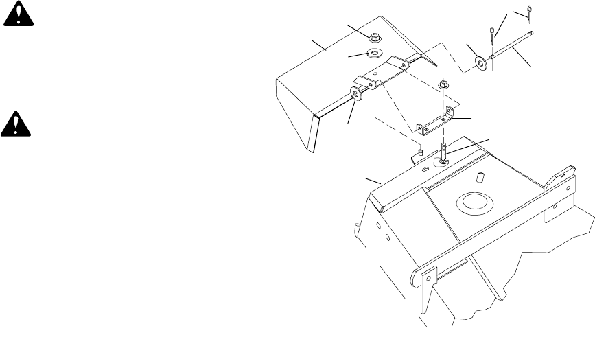
Discharge Chute Installation (Figure 21)
Secure chute with hold-down locknut (1) and washer
(8).
CD3540A
4
5
7
3
6
2
8
8
7
1
8
1. Discharge chute
2. Mower frame
3. Deck bracket
4. 3/16 x 1” Cotter pin
5. 3/8 x 7-1/4” Pin
6. 3/8 NC x 3/4” Carriage bolt
7. 3/8 NC Flange locknut
8. 3/8” Flat washer
Figure 21. Discharge Chute Installation
Rear Caster Installation (Figure 22)
Remove cap screw (12) from caster y oke and wheel
(8) then remove all spacers, washers and spring.
Insert caster yoke and wheel (8) into tube of caster
arm (3). Install all spacers, washers and spring as
shown and tighten cap screw (12). Repeat for
remaining caster assembly.
Remove right and left belt shields (13). Install caster
assemblies one at a time. Remove cap screw (6) and
lockwasher (7) from the mower frame lug (2).
Place caster arm assembly outside frame lug as
shown. Place lockwasher (7) on cap screw (6) and
install in rear hole. Install cap screw (4) in front hole
and start flange locknut (5) on it. Tighten hardware.
Repeat for opposite side.
Install belt s hields, being sure to place blade wrench
(not shown) under left belt shield knob.


