WPMAN0141 (8/31/01)10
Top Link Adjustment (Figure 2)
B
A
1
CD3944
1. T ractor top link
A. Mower top link
attachment point
B. Mower hitch pin
Figure 2. Top Link Adjustment
When the cutting height is adjusted, adjust tractor top
link until mower top link attachment point A is aligned
vertically with mower hitch pin B.
Attaching Mower to Tractor (Figure 3)
CD3557D
1
9
1. T ractor top link
9. Floating top link
Figure 3. Check Chain & Top Link Adjustment
NOTE: Mower cannot be used with a quick hitch.
The standard 1-3/8” 6B spline driveline with a QD
yoke is used to connect mower to tractor.
Attach the mower hitch pins to lower tractor lift arms
and secure.
Attach tractor top link (1) to offset links (9). Connect
the driveline to the tractor PTO shaft.
WARNING
J Make sure spring-activated locking
pin or collar slides freely and is seated
firmly in tractor PTO spline groove.
Adjust the tractor lower 3-point arm anti-sway devices
to prevent mower from swinging side to side during
transport.
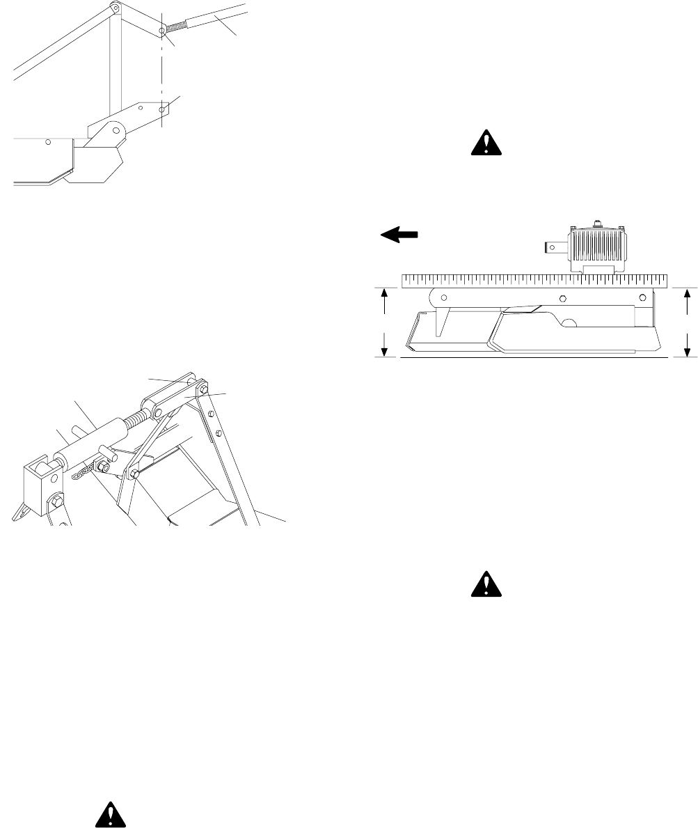
Cutting Height Adjustment (Figure 4)
IMPORTANT
J Avoid low cutting heights. Striking the
ground with blades produces one of the
most damaging shock loads a mower can
encounter. Allowing blades to contact
ground repeatedly will cause damage to
mower and drive.
WARNING
J Keep all persons away from operator
control area while performing adjust-
ments, service or maintenance.
CD3551B
B
A
FORWARD
Figure 4. Cutting Height Adjustment
Level mower from side to side. Check b y measuring
from mower frame to the ground at each deck rail.
Adjust, using tractor 3-point arm leveling device.
Best mowing results will be obtained with front of
mower level with or slightly lower than the rear.
Cutting height is controlled with tractor 3-point arms
and front and rear caster wheel adjustment. Optional
check chains are available.
WARNING
J Never go under ne a t h equipme nt low-
er e d to the ground or ra is e d, unles s it is
properly blocked and secured. Never
plac e any par t o f the body underneat h
equipment or between moveable parts
even when the engine has been turned off.
Hydraulic system leak down, hydraulic
system failures, mechanical failures or
movement of control levers can cause
equipment to drop or rotate unexpectedly
and cause severe injury or death. Follow
Oper a t or’ s Manua l instr uc tions for work-
ing under ne a t h and bloc k ing
re quir e m ents , or have work done by a
qualified de a le r.
To raise rear of mower, move caster adjustment
spacers under caster arms. Hex opening of blade
wrench fits bolts on top of caster shaft.
To raise front of mower, raise tractor 3-point arms,
shorten optional check chains or move spacers under
front caster wheel arms.


