Reference
CPS250 User Manual
13
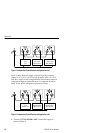
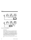
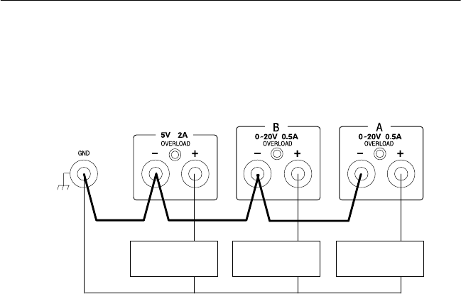
Figure 9 shows the connections for three ground referenced, positive
supplies.
Load 1
+5 V
Load 2
Zero to +20 V
Load 3
Zero to +20 V
Figure 9: Independent Ground-Referenced Applications (positive output)
Tracking Mode Applications
Series Tracking
When the A/B OUTPUTS selector is set to SERIES TRACKING, the
–output of the A variable supply is connected internally to the
+output of the B variable supply. When set to the SERIES TRACK-
ING mode, the output may be floating or ground referenced.
However, only one terminal of the two variable supplies may be
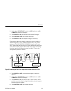
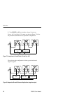
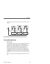
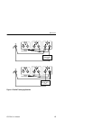
grounded. These options are shown in Figure 10 on page 14. The
output voltage and current are controlled by the A VOLTAGE and
A CURRENT controls. For convenience, set the B VOLTAGE and
B CURRENT controls fully clockwise to avoid the B supply shutting
down.
The 5 V fixed supply may be independently grounded or allowed to
float.


