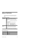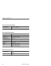
Reference
CPS250 User Manual
11
2. Set the A and B VOLTAGE controls to MIN and the A and B
CURRENT controls to midrange.
3. Turn POWER to ON, and set the desired A and B voltages.
4. Turn POWER to OFF, and connect the load(s).
5. Turn POWER to ON, and readjust voltages if necessary.
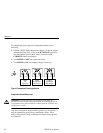
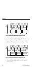
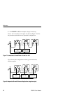
Figure 6 shows the power supply connected in series to produce a
variable output of 0 + 40 V, ground referenced, and –5 V, ground
referenced. The VOLTAGE and CURRENT controls are in series.
The V meter reads only one supply at a time and the mA meter reads
total current in either position. To read the total voltage the readings
from the A position and B position must be added. To set up this
configuration, proceed as follows:
Load 1
–5 V
Load 2
Zero to +40 V
Figure 6: Connecting the Two 0–20 V Supplies in Series to Product 0 to +40 V
1. Turn POWER to OFF, and connect the outputs as shown in
Figure 6.
2. Set the A and B VOLTAGE controls to MIN and the A and B
CURRENT controls to midrange.
3. Turn POWER to ON, and observe the V meter in the A and B
positions to set the desired voltage. Remember, the total output is
the sum of the two readings.
4. Turn tPOWER to OFF, and connect the loads.


