Getting Started
CPS250 User Manual
5
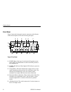
6. Milliampere Current Meter. This meter indicates the current level
of A or B output, depending on the position of the A/B meter
switch. The meter may be mechanically set for zero with the
slotted mechanical zero adjust disk below the center of the meter.
7. A/B Output Switch. Switches A and B outputs from
INDEPENDENT to TRACKING PARALLEL or TRACKING
SERIES operation. When the switch is in the TRACKING
position, A VOLTAGE and A CURRENT controls set the level of
both A and B outputs. B VOLTAGE and B CURRENT controls
are inoperative when the A/B OUTPUTS switch is set to the
TRACKING position.
8. B Voltage Control. Rotate to set voltage at B output terminals
when A/B OUTPUTS switch is in the INDEPENDENT position.
This control is inoperative when A/B OUTPUTS switch is in the
TRACKING position.
9. B CURRENT Control. Rotate to set current level available at B
output when A/B OUTPUTS switch is in INDEPENDENT
position. Control is inoperative when A/B OUTPUTS switch is in
the TRACKING position.
10. A CURRENT Control. Rotate to set current level available at A
output when A/B OUTPUTS switch is in the INDEPENDENT
position.
11. A VOLTAGE Control. Rotate to set voltage at A output terminals
when A/B OUTPUTS switch is in the INDEPENDENT position.
12. A Output. Positive (red) and negative (black) output for
independent 0 to 20 VDC, 0.5 A maximum. LED lights when
OVERLOAD current limit is reached or exceeded.
13. B Output. Positive (red) and negative (black) output for
independent 0 to 20 VDC, 0.5 A maximum. LED lights when
OVERLOAD current limit is reached or exceeded.
14. 5 V 2 A Output. Positive (red) and negative (black) output for
fixed 5 volts DC, 2 A maximum. LED lights when OVERLOAD
current limit is reached or exceeded.
15. Chassis Ground Connector. The green binding post is connected
through the power cord to the power receptacle ground.


