


User Connections 81
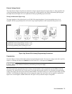
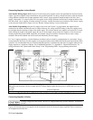
■ The first power supply in a linked connection is a "direct supply" connected to the controller via a GPIB cable. The
direct supply is the only supply connected directly to the bus and has a unique primary bus address.
■ The remaining power supplies are "linked supplies” connected to the direct supply via a serial-link cable. Each
linked supply has a unique secondary GPIB address and derives its primary address from the direct supply. You may
connect from 1 to 15 linked supplies to each direct supply.
Note The power supply is shipped from the factory with its GPIB address set to 5. The power supply primary
and secondary addresses can be changed from the front panel as described in "Chapter 2 - Remote
Programming" of the "Programming Guide". For power supply GPIB interface capabilities, see Table
1-5 in Chapter 1 of this guide.
ó
ì
ö
ú
÷
ø
A
B
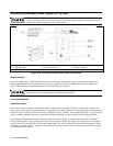
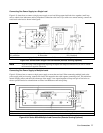
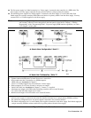
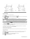
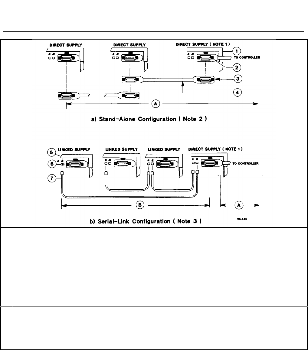
From 1 to 16 direct supplies may be connected to 1 controller GPIB interface.
Tighten connector thumbscrews by hand. Do not use a screwdriver.
Do not stack more than 3 connectors on a GPIB receptacle.
GPIB cable (see Accessories in Chapter 1)
From 1 to 15 linked supplies may be connected to 1 direct supply.
Either receptacle (Jl or J2) may be used as an input or an output.
Serial Link Cable (see Accessories in Chapter 1), 2 meters. 1 is supplied.
Maximum total length of all GPIB cables (including controller) not to exceed 20 meters.
Use caution with individual lengths over 4 meters.
Maximum total length of all serial cables not to exceed 30 meters.
1.
2.
3.
NOTES:
A direct power supply is connected to the controller interface and must have a unique primary GPIB bus address.
The stand-alone configuration uses only direct supplies connected to the controller interface.
The linked configuration uses 1 or more linked power supplies connected to each direct supply. Each linked supply has
a unique secondary GPIB bus address and derives its primary address from the direct supply.
Figure 4-6. Controller Connections