


User Connections
76
OVP Considerations
The power supply OVP circuit senses voltage near the output bus bars, not at the load. Therefore the signal sensed by the OVP
circuit can be significantly higher than the actual voltage at the load. When using remote sensing, you must program the OVP
trip voltage high enough to compensate for the voltage drop between the output bus bars and the load.
Output Rating
In remote sense applications, the voltage drop in the load leads subtracts from the available load voltage. As the power supply
increases its output to overcome this voltage drop, the sum of the programmed voltage and the load-lead drop may exceed the
power supply’s maximum voltage rating. This will not damage the supply, but may trip the OV protection circuit, which senses
the voltage at the output bus bars. When the supply is operated beyond its rated output the performance specifications are not
guaranteed, although typical performance may be good.
Stability
Using sensing under unusual combinations of load lead lengths and large load capacitances may cause your application to form
a low-pass filter, which becomes part of the voltage feedback loop. The extra phase shift created by this filter can degrade the
supply’s stability, resulting in poor transient response. In severe cases, it may cause oscillation. To minimize this possibility,
keep the load leads as short as possible and tie wrap them together.
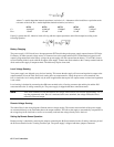
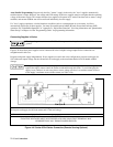
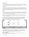
In most cases, following these guidelines will eliminate problems associated with load lead inductance. However, if a large
bypass capacitor is required at the load and load-lead length cannot be reduced, then a sense-lead bypass network may be
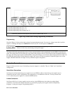
needed to ensure stability (see Figure 4-5b).
The voltage rating of the 33 µF capacitors should be about 50% greater than the anticipated load-lead drop. Addition of
the 20 Ω resistors will cause a slight voltage rise at the remote sensing points. For utmost voltage programming accuracy,
the supply should be recalibrated with the DVM at the remote sensing points (see “Appendix A - Calibration”). In
addition, the sense protect resistors inside the power supply may have to be removed. (If you need help with a stability
problem, contact an Support Engineer through your local Agilent Sales and Support offices.)
Load Leads
ó Remote Sense Points
C1, C2 = 33µF
C3 = Load bypass capacitor
Rl, R2 = 20 Ω, 1%
Figure 4-5b. Series 668xA Sense Lead Bypass Network
Output Noise
Any noise picked up on the sense leads may appear at the output of the supply and can adversely affect the voltage load
regulation. Use shielded twisted pairs for the sense leads and route them parallel and close to the load leads. Ground the
shields only at the power-supply end, utilizing the signal ground binding post. Do not use a shield as one of the sense
conductors. Bundle or tie-wrap the load leads to minimize inductance and reduce noise pickup.
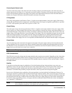
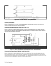
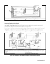
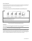
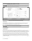
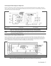
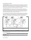
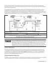
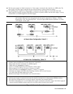
Operating Configurations
Figure 4-5c through Figure 4-5e show the various configurations for connecting to the load. Figure 4-5f shows how to
connect an external voltage source for analog programming.