


User Connections 57
4
User Connections
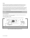
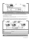
Rear Panel Connections (All Models)
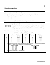
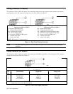
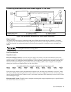
Make application load connections to the output terminals or bus bars, analog connector, and digital connector as shown on
the rear-panel drawing for your model power supply. These connections are organized by series as follows:
l Series 664xA and 665xA
l Series 667xA
l Series 668xA
Make controller connections (GPIB and serial link) as shown in Figure 4-6 at the end of this chapter.
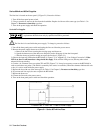
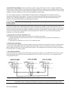
Load Wire Selection (All Models)
Fire Hazard To satisfy safety requirements, load wires must be large enough not to overheat when
carrying the maximum short-circuit current of the power supply. If there is more than one load, then
any pair of load wires must be capable of safely carrying the full-rated current of the supply. With
the larger-capacity supplies (such as Series 668xA), use of two or more load wires in parallel may be
required.
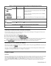
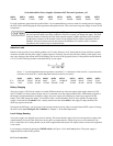
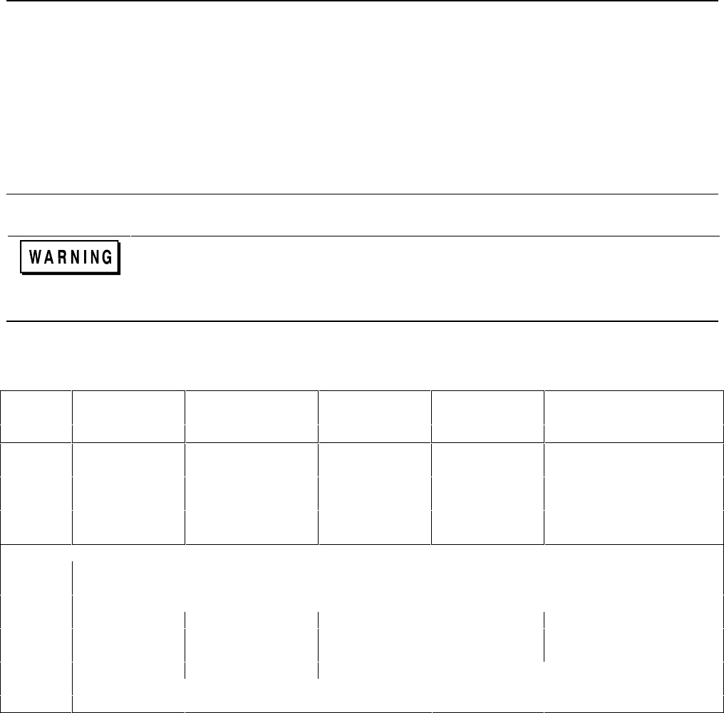
Table 4-1 lists the characteristics of AWG (American Wire Gauge) copper wire.
Table 4-1. Stranded Copper Wire Capacity and Resistance
AWG
Ampacity
l
Resistance
2
AWG
Ampacity
1
Resistance
2
No.
(Ω/m)
No.
(Ω/m)
14 25 0.0103 2 140 0.00064
12 30 0.0065 1/0 195 0.00040
10 40 0.0041 2/0 225 0.00032
8 60 0.0025 3/0 260 0.00025
6 80 0.0016 4/0 300 0.00020
4 105 0.0010
NOTES:
1. Ampacity is based on 30 °C ambient temperature with conductor rated at 60 °C. For ambient temperature other
than 30 °C, multiply the above ampacities by the following constants:
Temp (°C) Constant
Temp (°C) Constant
21-25 1.08 41-45 0.71
26-30 1.00 46-50 0.58
31-35 0.91 51-55 0.41
36-40 0.82
2. Resistance is nominal at 75 °C wire temperature.