


User Connections 79
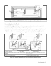
Program each power supply as an independent supply. If two supplies are used in series operation, each supply can be
programmed to deliver 50% of the total output voltage. Set the current limit of each power supply to the maximum that the
load can handle without damage.
If one supply experiences a desired shutdown condition (such as caused by overtemperature or overcurrent), it does not
automatically shut down the other supply. You must first enable remote inhibit (RI) and discrete fault indicator (DFI)
operation. It is recommended that you use the RI and DFI functions to automatically shut down both supplies whenever one
supply experiences a shutdown condition. See "Fault/Inhibit operation" in "Appendix D - Digital Port Functions" for wiring
information and "Questionable Status Group" in the "Programming Guide" for programming information.
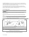
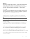
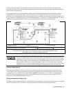
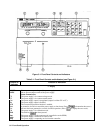
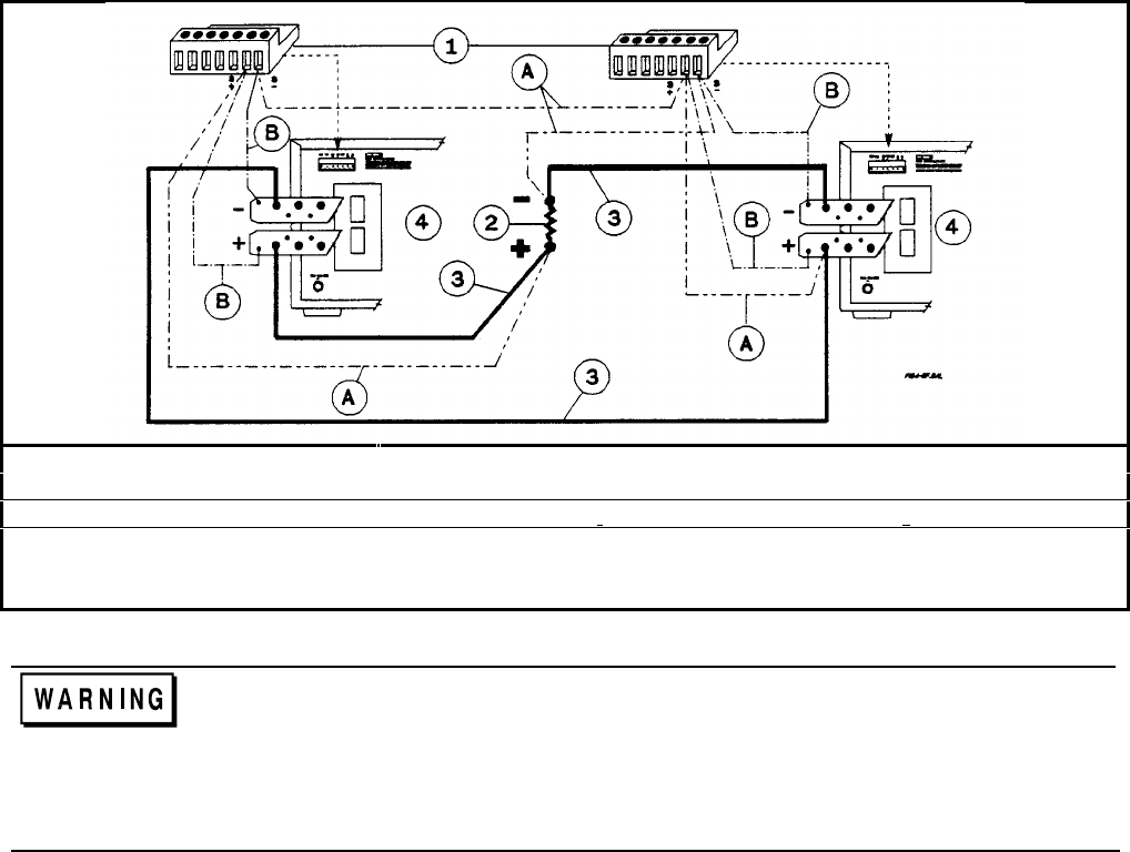
Analog Connector ó Load ì Load Connection
ö Program each supply for full load current and 1/2 the load voltage
A Connect for remote sensing (optional) B Connect for local sensing (default)
WARNING
FLOATING VOLTAGES MUST NOT EXCEED ±60 VDC. NO OUTPUT TERMINAL MAY
BE MORE THAN 60 V FROM CHASSIS GROUND.
Figure 4-5f. Series 668xA Series Connection (Remote Sensing Optional)
Each power supply has a reverse voltage protection diode across its output. If the fan in one of the
series power supplies shuts down for any reason (such as a fan circuit defect or loss of ac power), the
supply may severely overheat due to current forced through its reverse current diode by the functioning
supply. This possibility can be eliminated by use of the Rl/DFI functions previously noted. Also, if a
reverse voltage is applied across a functioning supply, it has no control over the current conducted
through this diode. To avoid damaging the supply, never connect it in such a way that a reverse voltage
can force it to conduct current in excess of the supply’s maximum rated current. (see Table 1-4b)
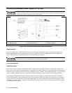
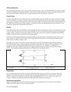
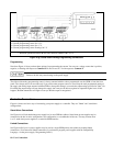
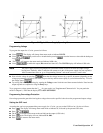
External Voltage Control
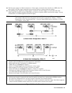
The setup shown in Figure 4-5g allows an external dc voltage to program the power supply output. A zero-to-full scale
voltage applied to the voltage programming input produces a proportional zero-to-full scale output voltage. The voltage
programming source is referenced to the programming Common P (↓P) terminal. A zero-to-full scale voltage applied to
one of the current programming inputs produces a proportional zero-to-full scale output current. See Figure 4-1 for an
explanation of these programming input connections.
Wiring Considerations (Figure 4-5g)
The input impedance of the analog input is over 30 kΩ. If the output impedance of your programming source is not negligible
with this, programming errors will result. Larger output impedances result in proportionally greater errors.