


User Connections
64
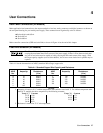
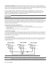
Auto-Parallel Programming. Program only the first ("master") supply in the series; the "slave" supplies automatically
track the master’s output. However, the voltage and OVP settings of the slave supplies must be set higher than the operating
voltage of the master supply. This ensures that the slave supplies will operate in CC mode. Functions such as status, voltage
readback, and current readback can still be read back individually for each supply.
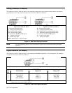
If a "slave" supply experiences a desired shutdown condition (such as overtemperature or overcurrent), it will not
automatically shut down all other supplies. You must first enable remote inhibit (RI) and discrete fault indicator (DFI)
operation. See "Fault/Inhibit Operation" in Appendix D for wiring information and "Questionable Status Group" in
Chapter 4 of the Programming Guide for programming information.
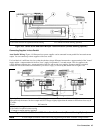
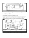
Follow the following operating precautions if you are connecting three of these models in auto-parallel.
You must use caution when connecting three Series 664xA or 665xA power supplies for auto-parallel operation. That is
because of the OVP crowbar circuits within these supplies. If the OVP circuit of the second "slave" trips, its crowbar circuit
will draw current from the other two supplies. Although some models can withstand this current, the higher-current models
in each series (particularly the Agilent 6651A) may be damaged in this situation. Use any of the following operating
techniques to avoid possible problems.
1. Program Slave 2 OVP to the Maximum Level
The following technique minimizes the chance that the slave 2 OVP circuit will trip.
a. Program the OVP level of the master and of slave 1 to the desired protection level (below the maximum level
specified in Table 1-2).
b. Program the OV protection level of slave 2 to its maximum value.
2. Enable OCP on the Master
You can do this if the combination of all three supplies is being used in the CV mode and the CC mode is only being used as
a current limit. Enable OCP on the master supply. If the OVP on either slave trips it will drive the master into CC mode,
thereby tripping its OCP. This will shut down all three supplies. This technique will work unless the system is programmed
for very low (0.5 to 1.5) output voltages.
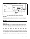
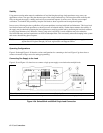
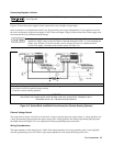
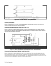
3. Insert Protection Diodes
If you connect the slave 2 supply to the load through a series diode (see Figure 4-3e), its OVP circuit will not draw current
from other supplies. Be certain to increase the programmed CV level of slave 2 by at least 0.7 V to compensate for the
voltage drop in the diode.
Figure 4-3e. Using Series Diodes with Series 664xA & 665xA Auto-Parallel Operation
Note Removing or disabling the power supply OVP crowbar SCR is another possibility. For further
information, contact a Agilent Service Engineer through your local Agilent Sales and Support Offices.