


Chapter 3 Front-Panel Operation
Remote Voltage Sensing at the Front and Rear Terminals
50
Stability
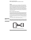
Using remote sensing under certain combinations of load lead lengths and
large load capacitances may cause your application to form a filter, which
becomes part of the voltage feedback loop. The extra phase shift created by
this filter can degrade the power supply’s stability, resulting in poor transient
response or loop instability. In severe cases, it may cause oscillations. To
minimize this possibility, keep the load leads as short as possible and twist
them together. As the sense leads are part of the power supply’s programming
feedback loop, accidental open-connections of sense or load leads during
remote sensing operation have various unwanted effects. Provide secure and
permanent connections.
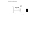
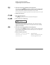
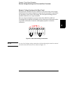
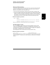
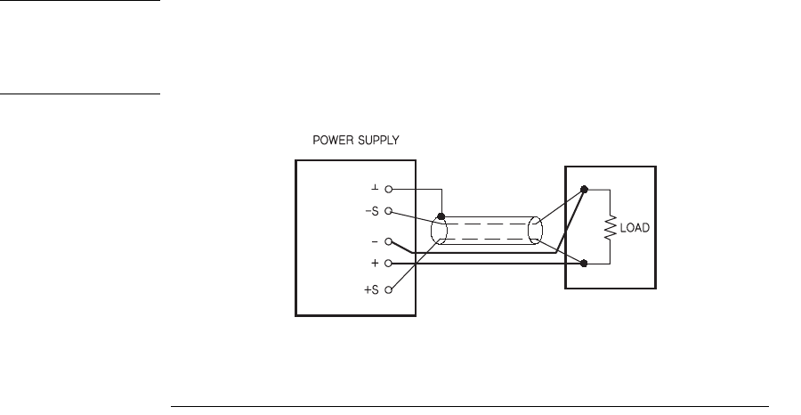
Remote Voltage Sensing Connections
Connections between the power supply sensing and output terminals should
be removed, and using shielded two-wire cable, the power supply sensing
terminals should be connected to the load as shown in Figure 3-2. Do not use
the shield as one of the sensing conductors and the other end should be left
unconnected. Connect one end of the sensing lead shield to the chassis ground
(
^) only. Opening a sensing lead causes the power supply output voltage to
decrease at the load leads. Observe polarity when connecting the sensing leads
to the load.
For local voltage sensing connections, the (+) and (-) sense terminals must be
connected to the (+) and (-) output terminals respectively.
Note When you make the remote voltage sensing connections at the front or rear panel
terminals, make sure to disconnect all the connections to the load and sense leads
at the other end terminals. Do not make the sensing connections at both front and
rear terminals at the same time. It will cause to damage the power supply seriously.
Figure 3-2. Remote Voltage Sensing Connections