


Chapter 7 Tutorial
Overview of Agilent E3633A and Agilent E3634A Operation
147
7
Overview of Agilent E3633A and Agilent E3634A Operation
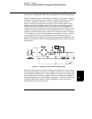
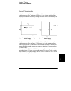
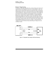
The basic design technique, which has not changed over the years, consists of
placing a control element in series with the rectifier and load device. Figure
7-1 shows a simplified schematic of a series regulated supply with the
phase-controlled pre-regulator described as a power switch and the series
element depicted as a variable resistor. The phase-controlled pre-regulator
minimizes the power dissipated at the series element by maintaining the
voltage drop across the series element at a low and constant. Feedback control
circuits continuously monitor the output and adjust the series resistance to
maintain a constant output voltage. Because the variable resistance of Figure
7-1 is actually one or more power transistor operating in the linear (class A)
mode, supplies with this type of regulator are often called linear power
supplies. Linear power supplies have many advantages and usually provide the
simplest most effective means of satisfying high performance and low power
requirements.
Figure 7-1. Diagram of Simple Series Power Supply
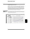
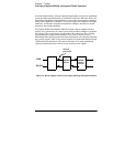
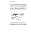
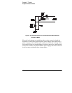
This power supply has two ranges, allowing more voltage at a lower current.
To maintain the voltage across the pre-regulator efficient in accordance with
the demands imposed by the dc output voltage and current of the supply, this
power supply also uses the pre-regulator which is controlled by transformer
tap switching before the rectifier bridge in the Figure 7-1. This is one of several
techniques using semiconductors for preregulation to reduce the power
dissipated across the series element.