


Chapter 3 Front-Panel Operation
Programming Overvoltage Protection
44
3 Clear the overvoltage condition and exit this menu.
Now, when you press key again, the “DONE” message is displayed for a
se co nd an d t he
OVP annunciator will not blink any more. The output will return
to meter mode.
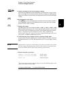
• Adjust OVP trip level
1 Raise the OVP trip level.
Press key and turn the knob to raise the OVP trip level.
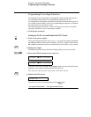
2 Move to the OVP CLEAR mode.
Press key to move to the OVP CLEAR mode. The “OVP ON” message
appears on the display. Turn the knob to the right until the above message
appears on the display.
3 Clear the overvoltage condition and exit this menu.
Now, when you press key again, the “DONE’’ message is displayed for
a second and the
OVP annunciator will not blink any more. The output will
return to the meter mode.
• Remote interface operation:
VOLT:PROT {<voltage>|MIN|MAX} Set the OVP level
VOLT:PROT:STAT {OFF|ON) Disable or enable the OVP circuit
VOLT:PROT:CLE Clear the tripped OVP circuit
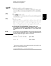
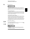
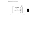
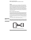
Note The power supply’s OVP circuit contains a crowbar SCR, which effectively shorts the
output of the power supply whenever the overvoltage condition occurs. If external
voltage source such as a battery is connected across the output, and the overvoltage
condition inadvertently occurs, the SCR will continuously sink a large current from
the source; possibly damaging the power supply. To avoid this a diode must be
connected in series with the output as shown in Figure 3-1 on next page.
OVP
OVPOVP
OVP CLEAR
Over
Voltage
Over
Voltage
Over
Voltage
Over
Voltage
Over
Voltage
Over
Voltage
Over
Voltage
Over
Voltage