


CNT-SVX07C-EN 51
Chapter 6
Status indicators for
operation and
communication
This chapter describes the operation and communication status indica-
tors on the Tracer ZN521 controller, including:
• A description of the location and function of the Test button and Ser-
vice pin button and the light-emitting diodes (LEDs) located on the
controller
• A complete list of the diagnostics that can occur, their effect on con-
troller outputs, and an explanation of how diagnostics are cleared and
the device restored to normal operation
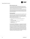
Test button
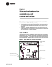
The Test button is used to perform the manual output test (see “Manual
output test” on page 52), which verifies that the controller output devices
are operating properly. It is located on the Tracer ZN521 circuit board as
shown in Figure 19. You must remove the cover to access the Test button.
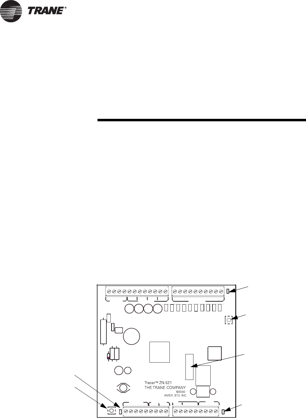
Figure 19. Tracer ZN521 zone controller circuit board
G
reen
(
status
)
LED
Test button
Neuron ID label
Ye ll ow
(communication)
LED
Red (service) LED
Service pin button