


Chapter 1 Overview and specifications
4 CNT-SVX07C-EN
Agency listing/compliance
CE—Immunity: EN 50082-1:1997; EN 50082-2:1995
CE—Emissions: EN 50081-1:1992 (CISPR 22) Class B
UL and C-UL 916 listed: Energy management system
UL 94-5V (UL flammability rating for plenum use)
FCC Part 15, Class A
ASHRAE Cycle 1 & Cycle 2 control sequences
Additional components
The Tracer ZN521 zone controller requires the use of additional compo-
nents for monitoring and proper control of the associated equipment. The
use of specific components depends on the application. These components
are not included with the Tracer ZN521 zone controller.
Power transformer
Use a UL-listed Class 2 power transformer supplying a nominal 24 Vac
(19–30 Vac) to power both the Tracer ZN521 zone controller (14 VA) and
its associated output devices, including relays and actuators, to a maxi-
mum of 12 VA per output utilized.
Water, duct, and outdoor-air temperature sensors
Temperature sensors must be Trane 10 kΩ (at 25°C) thermistors. Enter-
ing water and discharge air inputs may use a sealed temperature sensor
(part number 4190 1100).
Binary input switching devices
Occupancy, condensate overflow, low-coil-temperature, and fan status
inputs accept switching devices that may have normally open or normally
closed dry contacts.
Output devices
Output devices connected to the Tracer ZN521 binary outputs cannot
exceed 12 VA (0.5 A) current draw at 24 Vac.
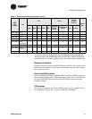
Zone temperature sensors
Table 1 shows the Trane zone temperature sensors that are supported by
the Tracer ZN521 zone controller.
Valve actuators
Valve actuators cannot exceed 12 VA draw at 24 Vac. For two-position
valves, use actuators with on/off action, and with a spring action that