


Chapter 4 Input/output functions and wiring for typical applications
20 CNT-SVX07C-EN
is established and then is no longer present, the controller generates a
Generic AIP Failure diagnostic.
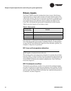
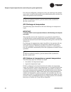
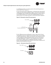
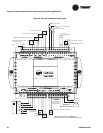
For the CO
2
measurement configuration, a 4–20 mA sensor must be hard-
wired to the AI4 terminal as shown in Figure 5. The sensor will transmit
a 0–2000 ppm value to the BAS. This configuration has no direct effect on
Tracer ZN521 operation. If a valid value is established and then is no
longer present, the controller generates a CO
2
Sensor Failure diagnostic.
Figure 5. AI4 terminal wiring: CO
2
measurement
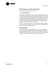
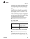
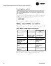
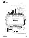
For the RH measurement configuration, either a hard-wired 4–20 mA
zone humidity sensor (see Figure 6) must provide a value to the controller
or a BAS communicates a value to the controller. The controller uses this
value to support the dehumidification function. (For more information,
see “Dehumidification” on page 47.) If a valid hard-wired or communi-
cated relative humidity value is established and then is no longer
present, the controller generates a Humidity Input Failure diagnostic and
disables the dehumidification function.
Figure 6. AI4 terminal wiring: RH measurement
Tracer ZN521
24 Vac
CO
2
sensor
(Trane 5010 0828 shown)
24 Vac
GND
Signal
Tracer ZN521
RH sensor