


Troubleshooting
CNT-SVX07C-EN 65
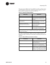
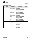
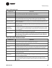
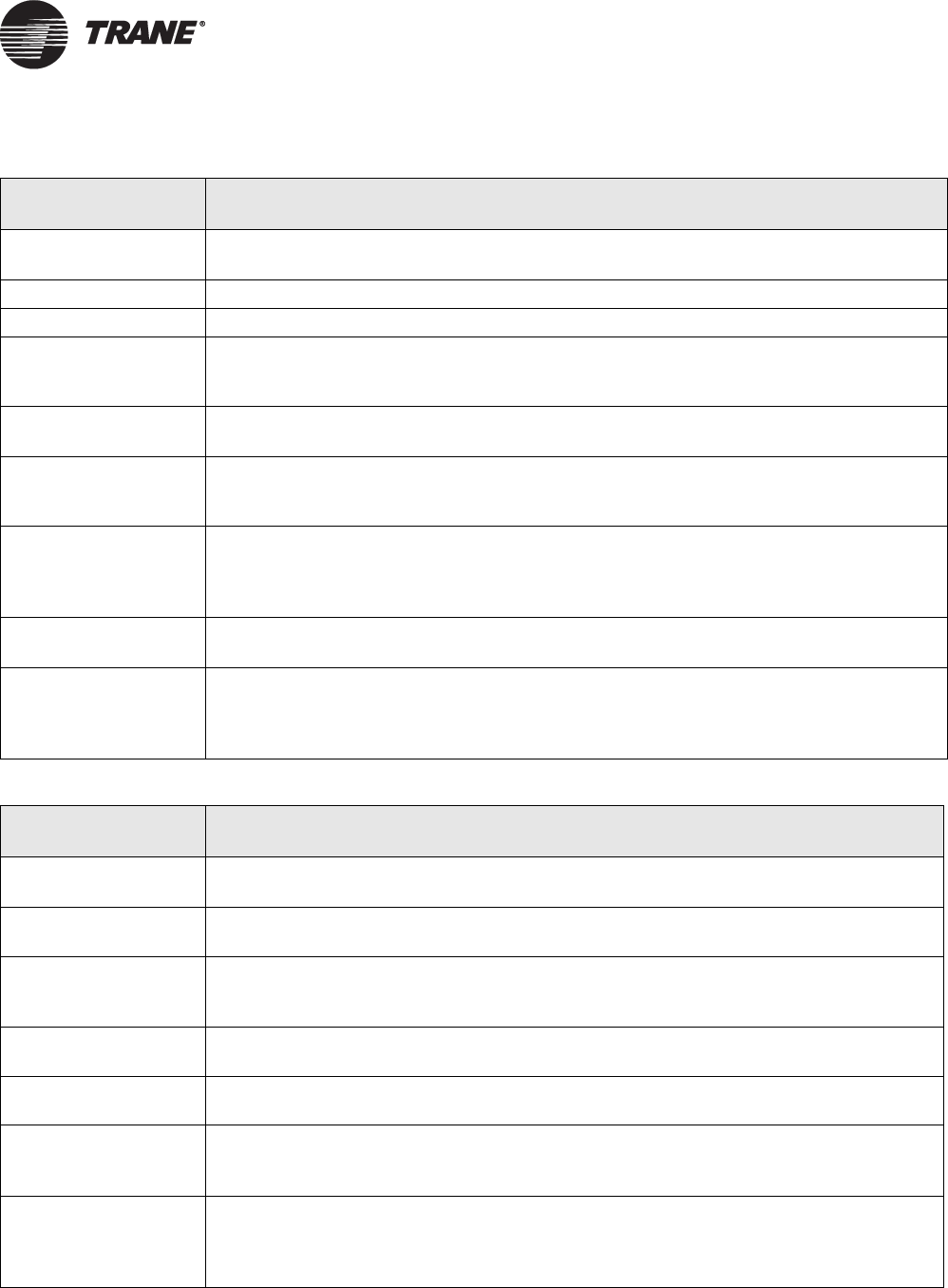
Table 19. Valves remain open
Probable cause Explanation
Unit wiring The wiring between the controller outputs and the valve(s) must be present and correct
for normal valve operation. Refer to applicable wiring diagram.
Failed end device The valves must be checked to ensure proper operations.
Normal operation The controller opens and closes the valves to meet the unit capacity requirements.
Manual output test The controller includes a manual output test sequence you can use to verify output oper-
ation and associated output wiring. However, based on the current step in the test
sequence, the values may not be open. refer to the “Manual output test” on page 52.
Diagnostic present Several diagnostics affect valve operation. For information about these diagnostics, see
Table 16 on page 59.
Unit configuration The controller must be properly configured based on the actual installed end devices and
application. If the unit configuration does not match the actual end device, the valves may
not work correctly.
Entering water
temperature
sampling logic
The controller includes entering water temperature sampling logic, which is automatically
initiated during 2-pipe and 4-pipe changeover if the entering water temperature is either
too cool or too hot for the desired heating or cooling. (See “AI1: Entering water tempera-
ture” on page 17.)
Valve configuration Make sure the valves are correctly configured, using the Rover service tool, as normally
open or normally closed as dictated by the application.
Freeze avoidance When the fan is off with no demand for capacity (0%) and the outdoor air temperature is
below the freeze avoidance setpoint, the controller opens the water valves (100%) to pre-
vent coil freezing. This includes unoccupied mode when there is no call for capacity or
any other time the fan is off.
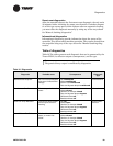
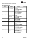
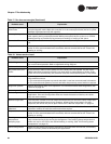
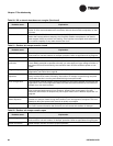
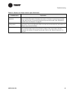
Table 20. DX or electric heat does not energize
Probable cause Explanation
Unit wiring The wiring between the controller outputs and the end devices must be present and cor-
rect for normal operation. Refer to applicable wiring diagram.
Failed end device Check the control contactors or the electric heat element, including any auxiliary safety
interlocks, to ensure proper operation.
No power to the
controller
If the controller does not have power, heat outputs do not operate. For the Tracer ZN521
controller to operate normally, you must apply an input voltage of 24 Vac. If the green
LED is off continuously, the controller does not have sufficient power or has failed.
Diagnostic present Several diagnostics affect DX and electric heat operation. For information about these
diagnostics, see Table 16 on page 59.
Normal operation The controller controls compressor or electric heat outputs as needed to meet the unit
capacity requirements.
Unit
configuration
The controller must be properly configured based on the actual installed end devices and
application. If the unit configuration does not match the actual end device, DX or electric
heat may not operate correctly.
Manual output test The controller includes a manual output test sequence you can use to verify output oper-
ation and associated output wiring. However, based on the current step in the test
sequence, the DX or electric heat outputs may be off. Refer to the “Manual output test”
on page 52.