Chapter 6 Status indicators for operation and communication
52 CNT-SVX07C-EN
Manual output test
The manual output test sequentially turns on and off all binary outputs
to verify their operation. The test overrides normal operation of the con-
troller, which is suspended while the test is being performed.
Use the manual output test to:
• Verify output wiring and operation
• Force the water valve(s) open to balance the hydronic system
• Clear diagnostics and restore normal operation (although not a pri-
mary function of the manual output test)
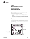
The manual output test is performed either by repeatedly pressing the
Test button to proceed through the test sequence or by using the Rover
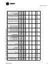
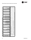
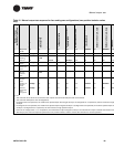
service tool. Table 11 on page 53 lists the outputs for non-face-and-bypass
unit configurations in the sequence in which they are verified; Table 12
on page 55 lists the outputs for face-and-bypass unit configurations in the
sequence in which they are verified.
The procedure is as follows:
1. Press and hold the Test button for 3 to 4 seconds, then release it to
start the test mode. The green (status) LED goes off when you press
the Test button, and then it blinks (as described in Table 14 on
page 57) when the Test button is released to indicate that the control-
ler is in manual test mode.
2. Press the Test button (no more than once per second) to advance
through the test sequence. Table 11 and Table 12 show the resulting
activities of the binary outputs.
Note:
The outputs are not subject to minimum on or off times during
the test sequence.


