


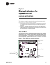

Chapter 6 Status indicators for operation and communication
56 CNT-SVX07C-EN
Service pin button
The Service pin button is located as shown in Figure 19 on page 51. The
Service pin button is used to:
• Identify a device (see “Identifying a device” in the Rover Installation/
Operation/Programming guide (EMTX-SVX01A-EN)
• Add a device to the active group (see “Adding a device” in EMTX-
SVX01A-EN)
• Verify PCMCIA communications (see “Verifying PCMCIA communi-
cations” in EMTX-SVX01A-EN)
• Make the green (status) LED “wink” to verify that the controller is
communicating on the link (see Table 14 on page 57 and “Setting the
Auto-wink option” in EMTX-SVX01A-EN)
Interpreting LEDs
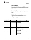
The red (service) LED on the Tracer ZN521 controller (see Figure 19 on
page 51) indicates whether the controller is capable of operating normally
(see Table 13).
Table 13. Red LED: Service indicator
LED activity Explanation
LED is off continuously when power
is applied to the controller.
The controller is operating normally.
LED is on continuously when power
is applied to the controller.
The controller is not working prop-
erly, or someone is pressing the Ser-
vice pin button.
LED flashes once every second. The controller is not executing the
application software because the net-
work connections and addressing
have been removed.
1
1
Restore the controller to normal operation using the Rover service tool. Refer to
EMTX-SVX01A-EN for more information.