


®
Chapter 3 Programming PID loops
24 CNT-APG002-EN
Follow these steps to program PID loops in PCL:
1. Make sure that the setpoint is within reasonable limits.
Use the MIN and MAX operators to set a ceiling and floor for the set-
point, as shown in lines 1 and 2 of Table 7 on page 25.
2. Run the PID calculation and store the result in an analog variable.
Do not place the DDC operation in an IF clause (*IFT or *IFF)
because the output can be unpredictable.
3. Define failure and other operation-dependent conditions.
These checks are called the fail-safe and enable/disable functions.
Typically, check for fan status and measured variable input failures.
4. If the failure or enable/disable conditions from step 3 are met, set the
analog variable to some default value.
5. Control the analog output with the result of the calculation.
You can follow this procedure for most PID applications. All PID applica-
tions require failure-mode conditions.
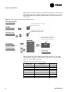
Table 7 on page 25 shows a PCL program with enable/disable and fail-
safe logic. Line 4 checks whether the fan is on. Line 5 checks whether the
analog input has failed. Line 6 prevents the PID loop from being used if
the fan is off or the analog input has failed. If either condition is met, the
analog output is set to –10.0 (closed) in line 7. If the fan is on and the ana-
log input has not failed, the PID loop controls the output in line 9.
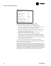
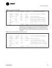
Table 6: PID settings in PCL
DDC LOOP # 4 HEAT VALVE
------------
PROPORTIONAL GAIN 4.00
INTEGRAL GAIN 1.00
DERIVATIVE GAIN 0.00
ACTION REVERS
PROPORTIONAL BIAS 0.0
MINIMUM OUTPUT VALUE 0.0
MAXIMUM OUTPUT VALUE 100.0
ERROR DIFFERENTIAL 0.5