


Pelco Manual C581M-B (1/04) 19
PROGRAMMING
This section applies only to programming the multiplexer. To program the
multiplexer server, refer to the server manual.
Programming allows you to configure the multiplexer from the KBD4002 for the way that
you want your system to operate. The multiplexer automatically selects the most common
operating parameters. However, some minimal programming may be required to make your
system work.
Programming of system, camera, and VCR setup; camera sequencing; and alarm and ac-
tivity detection are done through on-screen menus that are displayed on the main monitor.
A password can be enabled to prevent unauthorized access to the menus.
Programming of the picture-in-picture, and 4-, 9-, and 16-camera displays can be done
directly without going through menus.
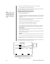
IMPORTANT NOTE
Before the keyboard can be used to control the multiplexer(s), perform the following steps at
the multiplexer(s) front panel.
1. Press the VIEW button for approximately three seconds. The basic SYSTEM Setup
menu appears.
2. The currently selected menu item blinks. Use the arrow buttons to highlight AD-
VANCED SETUP.
3. Press the +/- button. The Advanced System Setup menu appears. Skip steps 4 and 5 if
your system has only one multiplexer.
4. Use the arrow buttons to move the cursor to UNIT ID.
5. Press the +/- button to select the UNIT ID of the multiplexer.
6. Use the arrow button to move the cursor to COMM.TYPE.
7. In the polled communication mode (switch 4 OFF), one multiplexer must be the
master and all others slaves. In the non-polled mode (switch 4 ON), all multiplexers
must be slaves.
8. Use the arrow button to go to EXIT. Press the +/- button to exit the menu. The keyboard
can now be used to program the multiplexer(s).
NOTE:
Whenever a
multiplexer server is
installed, programming the
multiplexer
must be done
at the multiplexer front
panel. In this situation, the
multiplexer cannot be
programmed from the
+keyboard. The keyboard
can
only
be used to
program the multiplexer
server,
not
the multiplexer.
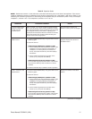
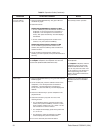
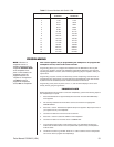
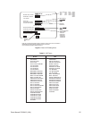
Table C. Camera Numbers with Switch 7 ON
Multiplexer Cameras
9-channel 16-channel
1 1-9 1-16
217-25 17-32
333-41 33-48
449-57 49-64
565-73 65-80
681-89 81-96
7 97-105 97-112
8 113-121 113-128
9 129-137 129-144
10 145-153 145-160
11 161-169 161-176
12 177-185 177-192
13 193-201 193-208
14 209-217 209-224
15 225-233 225-240
16 241-249 241-256