


FX2NC Series Programmable Controllers Introduction 1.
1-8
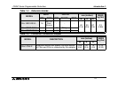
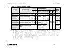
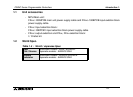
*1 : Internal 24V DC
*2 : When the voltage of the external DC power supply is 24V DC and 5V DC, the current is 70 mA and
100 mA, respectively.
*3 : Maximum number of I/O points per system Connection is allowed as far as the following condition is
satisfied:
(Actual number of I/O points of PLC) + (Number of points occupied by special extension blocks) +
(Number of points occupied by FX
2N
-16CCL-M: 8) + (32 x Number of remote I/O modules)
≤
256
*4 : For details, refer to the FX
2N
-64CL-M user's manual.
*5 : The value depends on the switch setting.
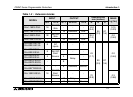
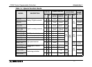
FX
2N
-1RM-E-
SET
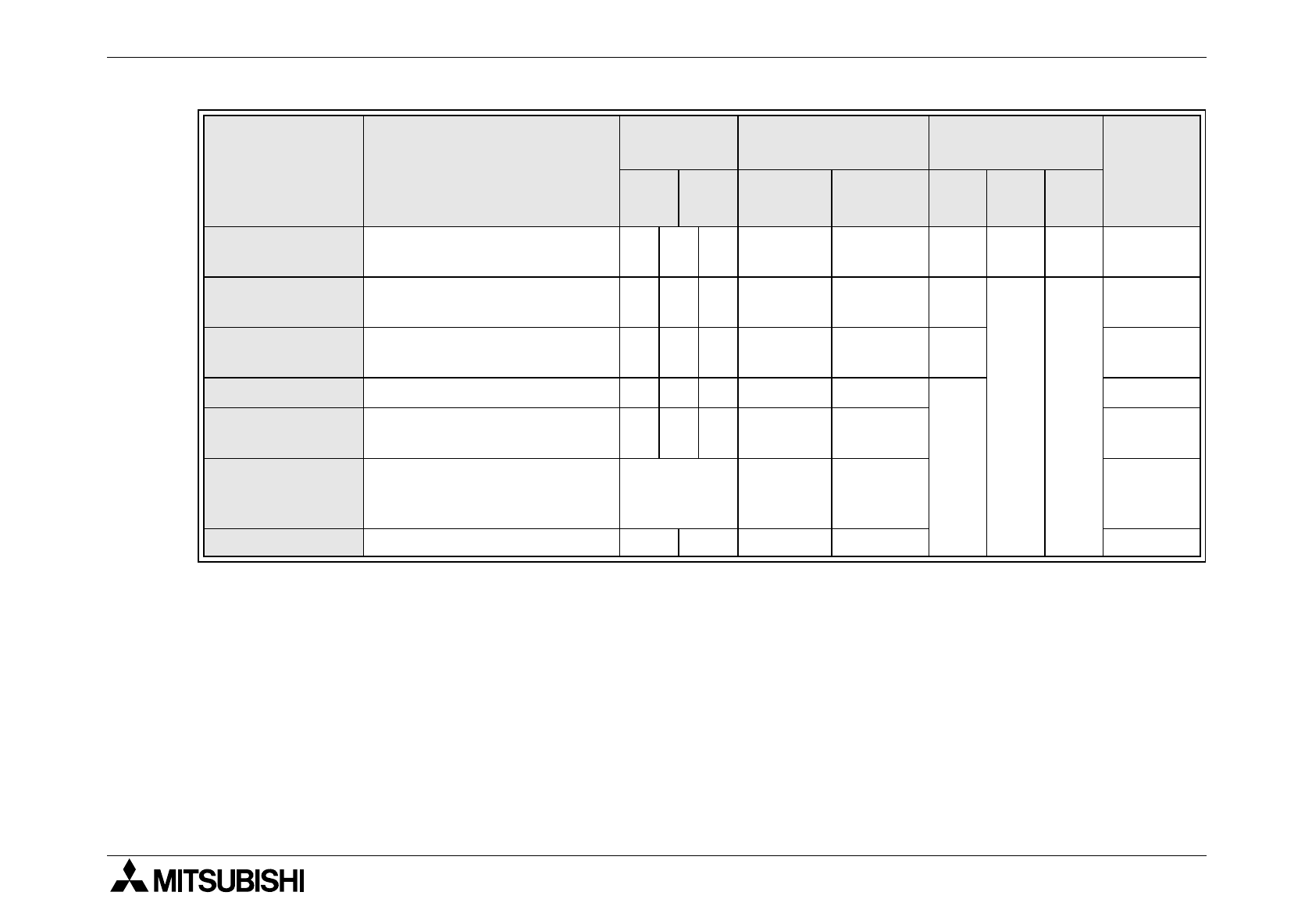
Programmable cam switch - 8 - - 5W
55
(2.1)
111
(4.4)
97
(3.8)
0.5(1.1)
FX
2N
-232IF RS-232C Interface block - 8 - 40mA 80mA
55
(2.1)
90
(3.5)
87
(3.4)
0.3(0.66)
FX
2N
-16CCL-M CC-Link Interface block *3 8 *3 - 150mA
85
(3.3)
0.4(0.88)
FX
2N
-32CCL CC-Link Interface block - 8 - 130mA 50mA
43
(1.7)
0.2(0.44)
FX
2N
-64CL-M CC-Link/LT Interface block *4 8 *4 190mA
25mA
*4
0.15
(0.01)
FX
2N
-16LNK-M
MELSEC-I/O LINK
Remote I/O system master
block
*5 200mA 90mA 0.5(1.1)
FX
0N
-16NT Net-mini interface 8 8 20mA 60mA 0.2(0.44)
Table 1.4 :Special function blocks
MODEL DESCRIPTION
NUMBER
OF I/O
POWER SUPPLY
DIMENSIONS
mm (inches)
MASS
kg (lbs)
I O
Internal
5V DC
External
24V DC
W H D