


084
084
/
CHAPTER 18: PROCESSOR
Peel the backing o the new thermal cooling pads in the kit and adhere the 4.
pads to the portions of the processor fan and heat sink assembly that cover
the processor.
Replace the processor heat sink (see “Replacing the Processor Heat Sink” on 5.
page 80).
Replace the magnesium cover (see “Replacing the Magnesium Cover” on 6.
page 52).
Replace the left and right brackets (see “Replacing the Brackets” on page 7. 47).
Replace the palm rest (see “Replacing the Palm Rest” on page 8. 44).
Replace the keyboard (see “Replacing the Keyboard” on page 9. 39).
Replace the center control cover (see “Replacing the Center Control Cover” 10.
on page 35).
Replace the compartment door (see “Replacing the Compartment Door” on 11.
page 14).
Replace the battery pack (see “Replacing the Battery Pack” on page 12. 11).
CAUTION: Before turning on the computer, replace all screws and ensure
that no stray screws remain inside the computer. Failure to do so may
result in damage to the computer.
Replacing the Processor
Follow the instructions in “Before You Begin” on page 1. 6.
CAUTION: Ensure that the cam lock is in the fully open position before
seating the processor. Seating the processor properly in the ZIF socket
does not require force.
CAUTION: A processor that is not properly seated can result in an
intermittent connection or permanent damage to the processor and ZIF
socket.
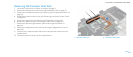
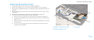
Align the pin-1 corner of the processor so that it points to the triangle on the 2.
ZIF socket, and insert the processor into the ZIF socket.
When the processor is correctly seated, all four corners are aligned at the
same height. If one or more corners of the processor are higher than the
others, the processor is not seated correctly.
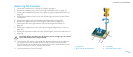
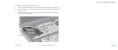
CAUTION: To prevent intermittent contact between the ZIF-socket cam
screw and the processor when removing or replacing the processor, press
to apply slight pressure to the center of the processor while turning the
cam screw.
Tighten the ZIF socket by turning the cam screw clockwise to secure the 3.
processor to the system board.
CAUTION: If the processor, processor fan and heat sink assembly, or
system board is replaced, use the thermal cooling pads provided in the
replacement kit to ensure that thermal conductivity is achieved. Do not
reuse the old thermal cooling pads.