


3-3
Integrated Services Adapter and Integrated Services Module Installation and Configuration
OL-3575-01 B0
Chapter 3 Removing and Installing the ISA and the ISM
Warnings and Cautions
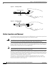
Each module has a bus connector that connects it to the router. The connector has a set of tiered pins in
three lengths that send specific signals to the system as they make contact with the module. The system
assesses the signals it receives and the order in which it receives them to determine if a module is being
removed from or introduced to the system. From these signals, the system determines whether to
reinitialize a new interface or to shut down a disconnected interface.
Specifically, when you insert a module, the longest pins make contact with the module first, and the
shortest pins make contact last. The system recognizes the signals and the sequence in which it receives
them.
When you remove or insert a module, the pins send signals to notify the system of changes. The router
then performs the following procedure:
1. Rapidly scans the system for configuration changes.
2. Initializes newly inserted port adapters or administratively shuts down any vacant interfaces.
3. Brings all previously configured interfaces on the module back to their previously installed state.
Any newly inserted interface is put in the administratively shutdown state, as if it was present (but
not configured) at boot time. If a similar module type is reinserted into a slot, its ports are configured
and brought online up to the port count of the originally installed module of that type.
Note Before you begin installation, read Chapter 2, “Preparing for Installation,” for a list of parts and tools
required for installation.
Warnings and Cautions
Observe the following warnings and cautions when installing or removing service adapters and service
modules.
Note If a port adapter lever or other retaining mechanism does not move to the locked position, the service
adapter is not completely seated in the midplane. Carefully pull the service adapter out of the slot,
reinsert it, and move the port adapter lever or other mechanism to the locked position.
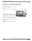
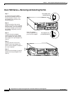
Caution To prevent jamming the carrier between the upper and the lower edges of the service module slot, and to
ensure that the edge connector at the rear of the ISM mates with the connection at the rear of the service
module slot, make certain that the carrier is positioned correctly, as shown in the cutaway in the “Cisco
7100 Series—Removing and Installing the ISM” section on page 3-5
Warning
When performing the following procedures, wear a grounding wrist strap to avoid ESD damage to the
card. Some platforms have an ESD connector for attaching the wrist strap. Do not directly touch the
midplane or backplane with your hand or any metal tool, or you could shock yourself.
Warning
Cisco 7100 series routers do not support OIR of the ISM. Failure to power down the router when
removing or replacing the ISM could cause serious equipment damage or electrical shock.