


1-7
Integrated Services Adapter and Integrated Services Module Installation and Configuration
OL-3575-01 B0
Chapter 1 Overview
LEDs
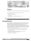
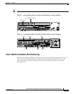
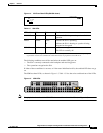
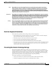
Figure 1-4 ISA Front Panel LEDs (SA-ISA shown)
The following conditions must all be met before the enabled LED goes on:
• The ISA is correctly connected to the backplane and receiving power.
• The system bus recognizes the ISA.
If either of these conditions is not met, or if the router initialization fails, the enabled LED does not go
on.
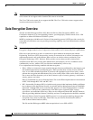
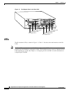
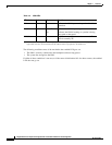
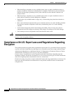
The ISM has three LEDs, as shown in Figure 1-5. Table 1-3 lists the colors and functions of the LEDs.
Figure 1-5 ISM LEDs
Note The physical orientation of the ISM LEDs is reversed from that of the ISA (see Figure 1-5).
Table 1-2 ISA LEDs
LED Label Color State Function
ENABLE Green On Indicates the ISA is powered up and enabled for
operation.
BOOT Amber Pulses
1
On
1. After successfully booting, the boot LED pulses in a “heartbeat” pattern to indicate that the ISA is operating. As
crypto traffic increases, the nominal level of this LED increases in proportion to the traffic level.
Indicates the ISA is operating.
Indicates the ISA is booting or a packet is being
encrypted or decrypted.
ERROR Amber On Indicates an encryption error has occurred.
This LED is normally off.
ENCRYPT/COMP
SA-ISA
ENABLE
BOOT
ERROR
17607
23774
EN
ERROR
BOOT
RESETSM-ISM