


Calibration
96
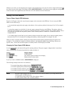
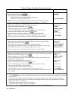
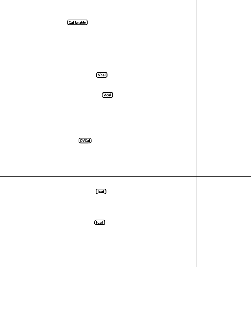
Table A-2. Typical Front Panel Calibration Procedure
Action
Display Response
Enabling the Calibration Mode
1. Begin calibration by pressing .
2. Enter calibration password from Entry keypad.
If password is correct the Cal annunciator will come on.
If password is incorrect, an error occurs
2
.
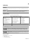
Note: The initial (factory-default) password is the model number of the power supply,
but it can be changed (see "Changing the Password" in Appendix A - Calibration).
PASWD
l
PASSWD ERROR
Entering Voltage Calibration Values
1. Make certain the DVM is the only load on the power supply.
2. Select the first calibration point by pressing
.
If the power supply is not in CV mode, an error occurs
3
3. Read the DVM and use the Entry keypad to enter the first voltage value.
4. Select the second calibration point by pressing
again.
5. Read the DVM and use the Entry keypad to enter the second voltage value.
Note: If one of the entered values is not within acceptable range, an error occurs.
The power supply is now holding the new voltage calibration constants in RAM.
(Meter mode)
VRDG1
WRONG MODE
(Meter mode)
VRDG2
(Meter mode)
CAL ERROR
Calibrating the OVP Trip Point
1. Make certain the voltage has been calibrated and there is no load on the power supply.
2. Select OVP calibration by pressing
.
3. Wait for the power supply to compute the OVP calibration constant.
If the supply goes unregulated or into CC mode during OVP calibration, an error occurs.
If the computed constant is out of acceptable range, an error occurs.
The power supply is now holding the new OVP calibration constant in RAM.
(Meter mode)
OVPCAL
CAL COMPLETE
NOT CV MODE
DOES NOT CAL
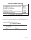
Entering Current Calibration Values
1. Make certain appropriate shunt resistor (see Table A-l) is the only load on the power supply.
2. Select the first calibration point by pressing
.
If the power supply is not in CC mode, an error occurs.
4
3. Wait for DVM reading to stabilize. Then read DVM and compute the first current value
(DVM reading ÷ shunt resistance).
4. Use Entry keypad to enter the first current value.
5. Select second calibration point by pressing
again.
(Meter mode)
IRDG1
WRONG MODE
(Meter mode)
(Meter mode)
IRDG2
6. Wait for DVM reading to stabilize. Then read DVM and compute the second
current value (DVM reading ÷ shunt resistance).
7. Use Entry keypad to enter the second current value.
Note: If the entered value is not within acceptable range, an error occurs.
Wait for the power supply to compute the new current calibration constants, which will be
stored in RAM.
(Meter mode)
(Meter mode)
CAL ERROR
CAL COMPLETE
1.
If CAL DENIED appears, then an internal jumper has been set to prevent the calibration from being changed. (See the
Service Manual.)
2.
If the active password is lost, the calibration function can be recovered by moving an internal jumper that defeats
password protection. However, this also will change all calibration constants to their factory-default values. (For more
information, see the Service Manual.)
3.
Program the output current to 10% of its rated output*
4.
Program the output voltage to l0% of its rated output*
* See applicable Output Ratings in "Chapter 1- General Information"